When finishing the simulation of RFlex model, the output files such as RFA, ERD, and SRD file can generate automatically. However, in case of a large RFI file and RFI with so many nodes, the animation speed can be very low compared to the previous version.
This function is useful such as the following cases.
•When the user simulates a RFlex model with the Output File Generator check option in RFlex, the user can generate output files after simulating the model whenever the user wants.
•When the user already had a rad file because the user simulated in the earlier version, the user does not need to simulate the RFlex model more in order to see the fast animation.
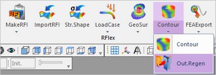
Figure 1 Out.Regen icon of the RFlex group in the Flexible tab
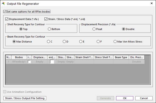
Figure 2 Output File Regenerator dialog box
•Set same options for all RFlex bodies
•If this option is checked, Regenerator sets the options for all RFlex bodies.
•This option is inactivated when RFlex bodies have a different type of Stress and Stain Shape for Shell.
•Displacement Data (*.rfa)
•If this option is checked, the user can recover the displacement using RFA file. (The default is checked.)
•If this option is unchecked, the user cannot acquire the recover data and see the displacement type contour animation. The user can see the displacement contour without this file, although it takes long time to play an animation.
•Strain / Stress Data (*.erd, *.srd)
•If this option is checked, the user can recover the strain and stress using ERD and SRD file. (The default is checked.)
•If this option is unchecked, the user cannot acquire the recover data and see the strain/stress type contour animation.
•Shell Recovery Type for Contour: Selects the recovery type of calculating stresses and strains on the shell element. This option is just reference input parameter. The recovery stress and strain data are not always the same with this selection. Because, stress and strain are calculated using the stress shape and strain shape data in the connected RFI file. If the RFI file doesn’t have both Top and Bottom data, then this reference input selection is ignored even if there are some shell type elements. The FEInfo. Page in the RFlex body property dialog shows what type is written in the connected RFI file.
•Top: Stresses and strains reported to the top surface of shell elements. (This is default.)
•Bottom: Stresses and strains reported to the bottom surface of shell elements.
•Beam Recovery Type for Contour: Selects the recovery type of calculating stresses and strains on the Beam2 element.
•Max. Distance: A point that has the longest distance between the neutral axis and the point is automatically selected in each element.
•C: The Stress and Strain are calculated on the C point.
•D: The Stress and Strain are calculated on the D point.
•E: The Stress and Strain are calculated on the E point.
•F: The Stress and Strain are calculated on the C point.
•Max. Von Mises Stress: A point that has the biggest Von-Mises stress value is automatically selected out of recovery points C, D, E, and F in every reporting time. (This is default from V9R4. Previous default is the Max. Distance.)
Note
RecruDyn GUI doesn’t show the element property information on the RFI file. Therefore, the user cannot check and modified the recovery points of the Beam element. The strain and stress are just calculated using the recorded values on the RFI file.
•Displacement Precision (*.rfa): Specify the precision of animation files (.rfa).
•Information
•In this dialog box, the user can select the RFlex body to generate the output files by checking the Sel column. The RFlex bodies in the model are automatically listed up.
o Empty: There are not any output files in the current directory after the simulation.
o Full: The output files have already generated in the current directory.
o Partial: The output files don’t have all kind of components. This option depends on the setting of the output file.
•Use Animation Configuration
•If the user wants to see the animation in the specific period, the user should use this option. It is useful that the time to generate output files can be reduced in case of the RFI file with so many nodes and the animation with so many frames.
•This option is available only when the user checks User Defined Animation in Animation Control Configuration as shown below. For more information, click here.
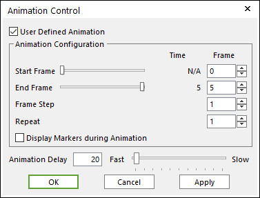
Figure 3 Animation Control [User Defined Animation]
•Output File Setting: Defines whether to include or not for the components at the output files. And it can be defined whether to write as Single (Float) or Double for data at the output files.
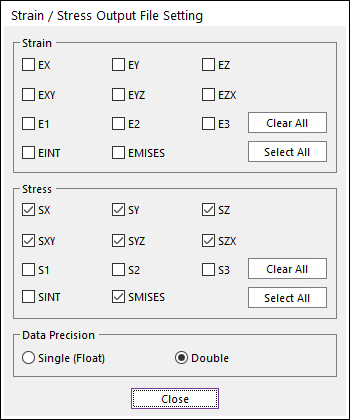
Figure 4 Output File Setting dialog box
Note
In the case of Eigenvalue analysis and FRA, the output files are generated for a current selected Mode Shape in Eigenvalue & FRA Animation group.