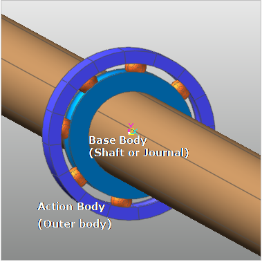
A ball bearing is defined between two bodies. When the user does modeling the ball bearing model, RecurDyn/Bearing should comply with the following rules:
•The journal or shaft part (Inner body) is set as a base body of ball bearing.
•The bearing part (Outer body) is set as an action body of ball bearing.
Figure 1 Base and action body of Ball Bearing
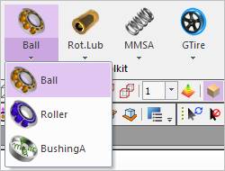
Figure 2 Ball Bearing Group icon of the Bearing group in the Toolkit tab
The user can create a bearing as follows.
•Point, WithDialog
•Point: Selects points on two bodies to define the location of the bearing.
•WithDialog: Modifies the property for the bearing with a dialog. The bearing is created with clicking OK. For more information, click here.
•Point, Direction, WithDialog
•Point: Selects points on two bodies to define the location of the bearing.
•Direction: Defines the direction for rotation of the bearing.
•WithDialog: Modifies the property for the bearing with a dialog. The bearing is created with clicking OK. For more information, click here.
•Body, Body, Point, WithDialog
•Body: Selects a base body as a shaft or journal.
•Body: Selects an action body as an outer body.
•Point: Selects points on two bodies to define the location of the bearing.
•WithDialog: Modifies the property for the bearing with a dialog. The bearing is created with clicking OK. For more information, click here.
•Body, Body, Point, Direction, WithDialog
•Body: Selects a base body as a shaft or journal.
•Body: Selects an action body as an outer body.
•Point: Selects points on two bodies to define the location of the bearing.
•Direction: Defines the direction for rotation of the bearing.
•WithDialog: Modifies the property for the bearing with a dialog. The bearing is created with clicking OK. For more information, click here.