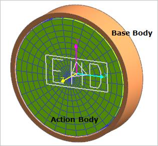
An MEHD is defined between two bodies. When the user does modeling the EHD model, the following rules should be complied:
•The bearing part (Outer body) is set as a base body of EHD.
•The journal or shaft part (Inner body) is set as an action body of EHD.
•If the Inner body is set to base body and Outer body is set to action body, incorrect simulation result shows up such as strange pressure contour.

Figure 1 EHD Rotational Lubrication
If the one of two bodies is RFlex, the user should find nodes to distribute the EHD pressure. In the RM of EHD, the z axis should be along the rotating axis and the x axis should indicate a node which is defined as a reference position for the circumference direction.
When the user makes EHD including a RFlex body, the user should comply with followings.
•The RFlex body should have the mesh format that “N” nodes have to exist along the circumference direction and “M” nodes have to exist along the bearing width by equal spaces. Therefore, the total number of nodes should be “N*M” nodes.
•It is recommended that there are nodes at the both ends in the z-axis direction of the action or base marker of RFlex body. Both ends are located at +L(width)/2 and -L/2 in the z-axis direction of the marker.
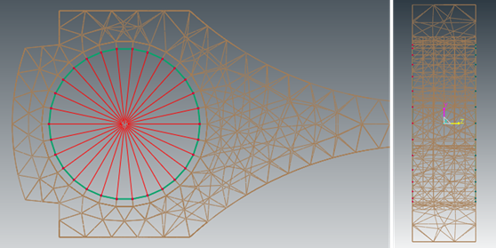
•For example, if there is a RFlex body including a hole in the center as base body of EHD System, it is recommended to make two master nodes by using RBE element like below figure.

Figure 2 Example in the case that RFlex body is base body in EHD system