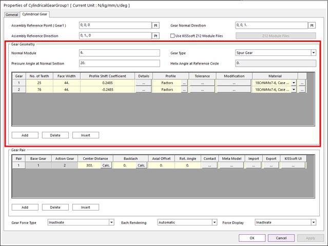
This section is to deine the geometry of the gear pair.

Figure 1 Properties of CylindricalGear dialog box (Gear Geometry)
•Normal Module: Normal module is the size unit that displays how big or small a gear is. It is the ratio of the gear's reference diameter divided by the number of teeth.
•Gear Type: Three types are supported. (Spur Gear, Helix Right Hand, Helix Left Hand)
•Pressure Angle at Normal Section: Normal pressure angle at the reference circle. It is defined as the angle between the pressure line and the plane tangent to the surface of the pitch. The pressure angle is 20 degrees for typical gear. For a higher number of teeth, lower pressure angle can be used to obtain higher contact ratios and insensitivity to center distance changes. Higher pressure angles improve strength and make it possible to use a fewer number of teeth without undercut. The contact ratio decreases in this situation and the radial forces increase.
•Helix Angle at Reference Circle: Helix angle at reference circle. If spur gear is used, this value is zero. The helix angle determines the axial forces direction. Helical gear produces less noise than the spur gear, but generates an extra bending moment and an axial force.
•No. of Teeth: Number of teeth of this gear. You can create Internal Gear by setting Number of Teeth of gear2 as minus value.
•Face Width: Gear face width. The face width would usually not be more than 10 to 20 times the normal module or not more than the pinion reference circle.
•Profile Shift Coefficient: The distance between the production pitch circle and the tool reference line. The tool is pulled further out of the material to create a positive profile shift generating a tooth that is thicker at the root and thinner at the tip The tool is pushed further into the material to create a negative profile shift resulting in the tooth being thinner and undercutting may occur earlier. Besides the effect on tooth thickness, the profile shift coefficient will also affect the sliding velocities. The total profile shift distribution affects the thickness of the tooth, sliding movements, and strength values.
•Details: For external gear, Inner Diameter is diameter of hole. For internal gear, Outer Diameter is diameter of outermost side circle of gear.

Figure 2 Gear Details dialog box
•Profile: Tooth profile can be defined according to related parameters. There are three types of methods for defining a tooth profile. If reference profile is defined from the data base list, related parameters are updated automatically.
•Factors
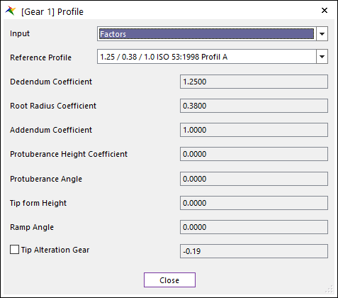
Figure 3 Gear Profile dialog box [Factors]
o Dedendum Coefficient: Defined the cutter’s dedendum that, with a topping tool, determines the tip circle.
o Root Radius Coefficient: Defines the cutter fillet radius. In a topping tool, the root radius cuts a tip rouding on the gear in most cases. The manufacturing process is simulated by KISSsoft Gear. In doing so, the effective undercut in the root of the tooth is calculated.
o Addendum Coefficient: Defines cutter addendum, which defines the gear root circle.
o Protuberance Height Coefficient: Defines the protuberance length, measured from the addendum. The protuberance is used as an artificial undercut to prevent a grinding notch from being created.
o Protuberance Angle: This value is usually smaller than the pressure angle. However, in the case of some special cutters, it may also be larger.
o Tip form Height: Defines the start of the straight flank / involute part of the tool with pressure angle. The height is measured from the tool reference line.
o Ramp Angle: Defines a ramp flank or a profile modification that is present in the cutter.
o Tip Alteration Gear: Tip alteration are calculated from the total profile shift to ensure that the tip clearance does not change. Tip clearance is the distance between the tip circle of one gear and the root circle of the other gear.
o Tip Radius Coefficient: Tip radius means the tip radius of the cutter which determines the radius of the root of the gear. Gear root radius means the gear radius of the root filet.
•Lengths: Parameters from Length input have same meaning from Factor. However, Coefficient parameter from Factor has proportional relationship with Module and Length parameter. For example, Dedendum equals Module multiplied by Dedendum Coefficient
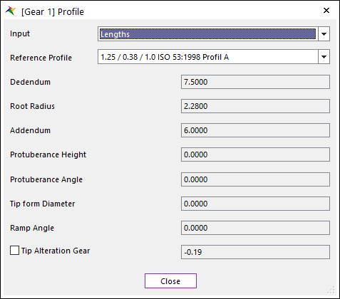
Figure 4 Gear Profile dialog box [Lengths]
•Diameter
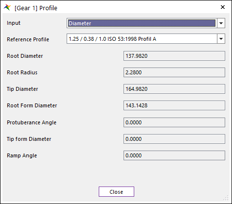
Figure 5 Gear Profile dialog box [Diameter]
o Root Diameter: Defines the diameter of a circle around the bottom (root) of the gear tooth spaces. It is same to Root Radius in RecurDyn/Gear.
o Root Radius: Defines the cutter fillet radius. In a topping tool, the root radius cuts a tip rouding on the gear in most cases. It is same to Hob Rack Radius in RecurDyn/Gear.
o Tip Diameter: Defines the overall diameter of the gear.
o Root Form Diamter: Defines the diameter which specifies the transition point between the usable involute profile and the fillet of the tooth.
•Tolerance: The toothing geometry is calculated for a backlash-free state. A slightly smaller tooth thickness is manufactured, to prevent the gears jamming in practice. This reduction in tooth thickness is known as the tooth thickness allowances.
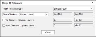
Figure 6 Gear Tolerance dialog box
•Tooth Tolerance Type: RecurDyn provides the tolerance type KISSsoft support.
•Tooth Thickness (Upper/Lower): Defines the allowance of Tooth Thickness. The upper tooth thickness allowance is the upper limit of the tooth thickness. The lower tooth thickness allowance is the lower limit of the tooth thickness. Default setting is that Tooth thickness calculated automatically.
Note
After changing the Tooth Tolerance and calculate backlash, the backlash changes with set tolerances. The backlash is calculated with several factors according to selected calculation method in KISSsoft e.g. DIN3967. After selecting the Tooth Tolerance Type such as DIN3967 h22, KISSsoft calculate Upper and Lower Allowance. With Upper and Lower Allowance, KISSsoft calculates Tooth Thickness Tolerance. (Tooth Thickness Tolerance = Upper - Lower allowance). Tooth Thickness Tolerance is taken into account for Backlash calculation. Calculated backlash is then taken into account for calculating tooth geometry.
•Tip Diameter (Upper/Lower): User can specify the tip diameter allowances if a non-topping tool has been defined. In contrast, the tip allowances for a topping tool are defined from the tooth thickness allowances.
•Root Diameter (Upper/Lower): Root diameter allowances are usually calculated from the tooth thickness allowances. In a gear cutting process, the gear backlash is produced by reducing the manufacturing distance of the tool. This is why the root diameter allowances depend on the tooth thickness allowances.
Note
The Gear Train dialog in DriveTrain Toolkit is created based on the KISSsoft User Interface. Some of the nomenclature is different from the RecurDyn Gear Toolkit. Below is the comparison of those parameters that has the same meaning but different names.
Delta Tooth Thickness from RecurDyn Gear Toolkit has similar gear geometry result with KISSsoft if its values is (Upper Tooth Thickness + Lower Tooth Thickness)/2.
|
KISSsoft |
RecurDyn |
|
Normal Module |
Module |
|
Pressure Angle at Normal Section |
Pressure Angle |
|
Helix Angle at Reference Circle |
Helix Angle |
|
Face Width |
Gear Width |
|
Profile Shift Coefficient |
Addendum Modification Coefficient |
|
Inner Diameter |
Hole Radius |
|
Dedendum Coefficient |
Dedendum Factor |
|
Root Radius Coefficient |
Hob Rack Radius Coefficient |
|
Addendum Coefficient |
Addendum Factor |
•Modification
•Tip Modification
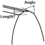
o Chamfer: Define the Length and Angle of Chamfer at tip. Refer to the image below.
o Rounding in Trasverse / Axial / Normal Section: Normal direction is normal to the tooth direction. Axial direction is parallel to the axis. Transvers direction is direction within transverse plane. If the gear type is spur gear, only transverse option is available. Refer to the image below.
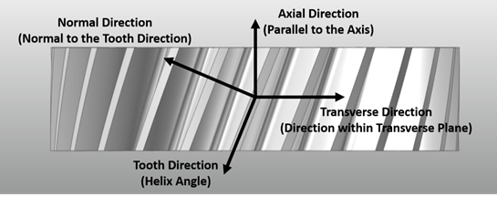
If you use Rounding in
Normal Section, the user input Radius is applied in normal section.
Refer to the image below.

If you use Rounding in Transverse Section, the user input Radius is applied in transverse section. Refer to the image below.

If you use Rounding in Axial Section, the user input Radius is applied in axial section. Refer to the image below.

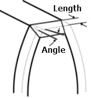
•Chamfer/Tooth End: Define the Length and Angle of Chamfer at tooth end. Refer to the image below.
•Profile/Tooth Modification: For more information, click here.
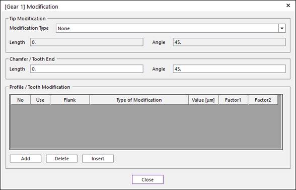
Figure 7 Modification dialog box
•Material: The materials displayed in the drop-down lists aretaken from the material data base KISSsoft support.
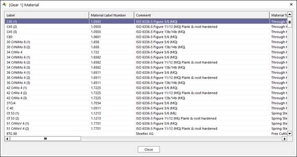
Figure 8 Gear Material dialog box