 , up to the tip circle, refers to the
theoretical involute. The same applies to the Root Relief.
, up to the tip circle, refers to the
theoretical involute. The same applies to the Root Relief.
Profile modifications are actually variations of the involute and are known as height corrections. The following sections describe which profile modifications are included in the KISSsoft system.
•Tip / Root Relief, Linear
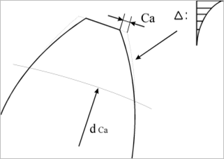
Tip relief on the driven gear reduces the impact on the entry, while tip relief on the driving gear reduces the impact on the exit. Tip reliefs are therefore usually applied to both gears.
Below figure illustrates Tip
Relief. The constantly increasing amount of material removed
in the transverse section, starting at , up to the tip circle, refers to the
theoretical involute. The same applies to the Root Relief.
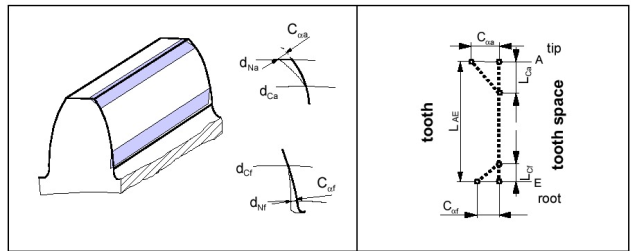
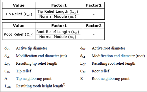
Figure 1 Linear Tip/Root Relief
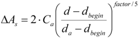
The KISSsoft input the size value
 in the Value input
field, for tip relief. The Coefficient 1 input field defines the quotient
from the calculated tip relief length
in the Value input
field, for tip relief. The Coefficient 1 input field defines the quotient
from the calculated tip relief length  and normal module
  . Similarly, to represent root
reliefs, input the values for
. Similarly, to represent root
reliefs, input the values for  and the quotient from
 and .
and .
•Tip / Root Relief, Arc-like
The method used here is similar to
the one used for a linear profile modification. The difference is that this
method involves approximating an arc of circle which starts at the point where
diameter intersects with the unchanged
tooth profile. The tangents of the arc of circle are identical to the tangent of
the unchanged tooth profile at this point. The benefit of this modification is
that the tangents do not change abruptly in the unchanged tooth form - circular
pitch approximation transition point.
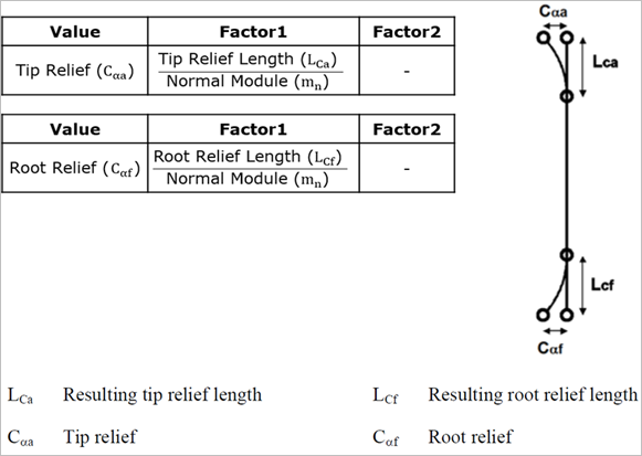
Figure 2 Arc-like Tip/Root Relief
•Tip / Root Relief, Progressive
The procedure used here is similar to the one used for a linear profile modification. The progressive profile modification is also detailed in the description of tooth form options.
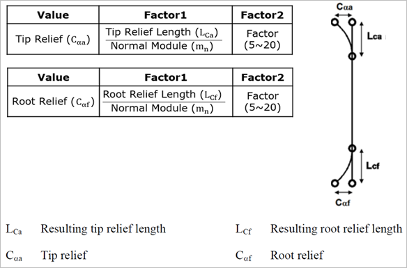
Figure 3 Progressive Tip/Root Relief
Tip:
In a progressive profile
modification, the tooth thickness is reduced from a starting diameter to the tip
(relief  on each flank as a tooth
thickness modification) in accordance with
on each flank as a tooth
thickness modification) in accordance with
The coefficient controls the course of the relief. A coefficient of 5 represents a linear relief. For more information, see also Figure below. If a coefficient greater than 5 is used, the progressive profile modification moves tangentially into the unmodified tooth flank.
This is the preferred option if larger reliefs are to be achieved. We do not recommend you use a coefficient of less than 5 (some of these lower values are simply ignored by the program). Coefficients greater than 20 are also ignored. In this case, a coefficient of 20 is used.
•Tip / Root Relief, with Transition Radius
Below figure shows tip and root
relief with transition radii. The constantly increasing amount of material
removed in the transverse section, starting at , up to the tip circle, refers to the
theoretical involute. The same applies to the root relief.
Figure 4 Tip/Root Relief with Transition Radius
Enter a Value for in the input field. In the
Factor 1 input field, enter the quotient from the calculated tip relief
length and normal module . In the Factor 2, input the
quotient from the transition radius in the tip area  and normal module . If coefficient 2 = 0, then is calculated in such a way
that
and normal module . If coefficient 2 = 0, then is calculated in such a way
that  = 0.8 * applies. The corresponding
coefficient 2 is calculated and applied. If coefficient 2 is so large that < 0.75 * applies, then is calculated in such a
way that = 0.75 * applies. The corresponding
coefficient 2 is calculated and applied. Similarly, to represent root reliefs,
input the values for and the quotient from and , and the quotient from
= 0.8 * applies. The corresponding
coefficient 2 is calculated and applied. If coefficient 2 is so large that < 0.75 * applies, then is calculated in such a
way that = 0.75 * applies. The corresponding
coefficient 2 is calculated and applied. Similarly, to represent root reliefs,
input the values for and the quotient from and , and the quotient from  and .
and .
•Profile Crowning(Barreling)
Profile crowning (barreling) is
where a constantly increasing amount of material is removed in the transverse
section in the direction of the tip and root circle, starting at the middle of
the calculated tooth flank length. Points A, E and the value  define the arc-like
progression.
define the arc-like
progression.

Figure 5 Profile Crowning (Barraling)
•Eccentric Profile Crowning
The definition of eccentric profile
crowning is the same as for eccentric crowning, but Factor 1 corresponds
to the diameter ratio ( )/(
)/( ). Here, you should note that the
modification is defined by the diameter, not by the length of path of contact.
Therefore, if you input a value of 0.5 for Factor 1, this will not
correspond to the profile crowning, which is symmetric to the center point of
the path of contact (
). Here, you should note that the
modification is defined by the diameter, not by the length of path of contact.
Therefore, if you input a value of 0.5 for Factor 1, this will not
correspond to the profile crowning, which is symmetric to the center point of
the path of contact ( ).
).
Factor 2 is used to define
the root relief from the tip relief. You can use Factor 2 to set a different
value for and . = 'Value'; = * 'Factor 2' then applies.

Figure 6 Eccentric Profile Crowning
•Pressure Angle Modification (value)
You define the pressure angle
modification in a similar way to tip/root relief. However, the difference
here is that the value  applies over the entire tooth
depth.
applies over the entire tooth
depth.
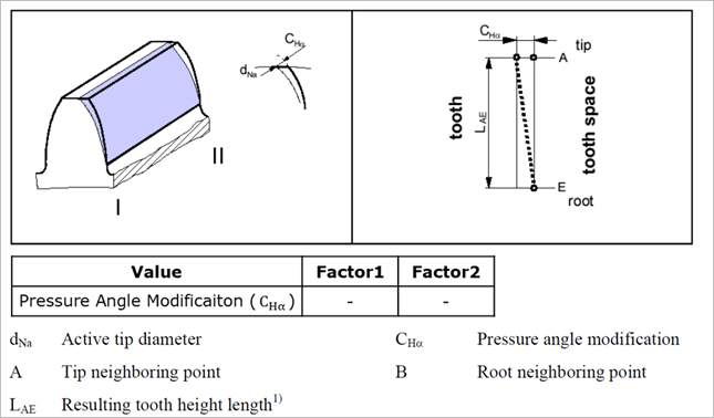
Figure 7 Pressure Angle Modification
Enter the value  in the Value input
field.
in the Value input
field.
A minute of arc is equal to 1/60 of one degree. In the Arc Minute Type, enter the arc minute value in the Factor 1 input field.
•End relief, linear I, II
A linear end relief is the constantly increasing removal of material from the tooth trace, starting from particular points, in the direction of the front and rear face surface. In this case, the numbers for I and II relate to both face surfaces.
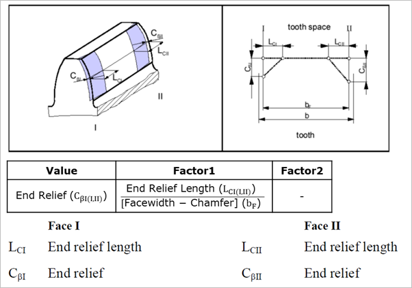
Figure 8 Linear End Relief I, II
This is why the KISSsoft system, go
to the Value input field and enter the value  , in the Coefficient 1 input
field, enter the quotient
, in the Coefficient 1 input
field, enter the quotient  where
where  is the facewidth minus
chamfer.
is the facewidth minus
chamfer.
•End relief, Arc-like I, II
An arc-like end relief is the constantly increasing removal of material from the tooth trace, starting from particular points, in the direction of the front and rear face surface. In this case, the numbers for I and II relate to both face surfaces
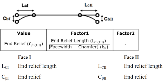
Figure 9 Arc-like End Relief I, II
This is why the KISSsoft system, go
to the Value input field and enter the value  , in the Coefficient 1 input
field, enter the quotient where
, in the Coefficient 1 input
field, enter the quotient where  is the facewidth minus
chamfer.
is the facewidth minus
chamfer.
•Helix Angle Modification, tapered or conical
You define the helix angle
correction in a similar way as end relief. However, the difference here is that
the mass  applies over the entire
facewidth.
applies over the entire
facewidth.
This is why the KISSsoft enter the
value  in the Value input
field.
in the Value input
field.
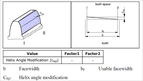
Figure 10 Helix Angle Modification, Tapered or Conical
If Conical Type removes
material towards  from
from  as on both side of gear tooth,
Parallel Type removes material towards opposite side of gear tooth as
(I-II) and (II-I).
as on both side of gear tooth,
Parallel Type removes material towards opposite side of gear tooth as
(I-II) and (II-I).
•Crowning
Crowning is where material is
removed constantly and symmetrically in the direction of the face surfaces,
starting from a common point and where the tooth trace remains constant. The
material is removed in an arc-like progression with the maximum at the  /2.
/2.
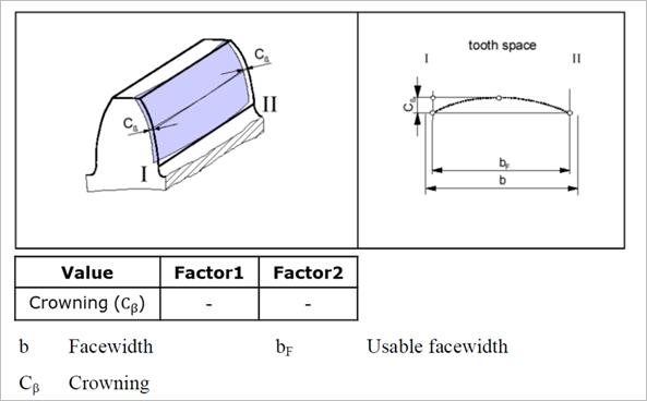
Figure 11 Crowning
In KISSsoft, go to the Value
input field and enter the value  .
.
•Eccentric Crowning
For eccentric crowning, the Value defines the amount of modification and the Factor 1 defines the modification position from the side I divided by the facewidth. The modification is defined as a part of arc that the center is located along the vertical line defined by the Factor 1. The radii are shown in the Information field according to your input. If you define the Factor 1 as 0.5, the modification is equivalent with general Crowning.
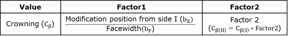
You can use Factor 2 to set a
different value for the modification on side II ( =
=  * Factor 2).
Figure 12 Eccentric Crowning
•Triangular End Relief I, II
The corners are broken.

Figure 13 Triangular End Relief I, II
This is why the KISSsoft enter the
Value  in the input field. Then go
to the Coefficient 1 input field and enter the quotient of
in the input field. Then go
to the Coefficient 1 input field and enter the quotient of  . Then go to the Coefficient 2
input field and enter the quotient of
. Then go to the Coefficient 2
input field and enter the quotient of  and facewidth b.
•Twist
Twist is the torsion of the transverse section profile along a helix. Usually, the angle increases in a linear progression from the start of the effective flank to its end. A positive directional torsion moves clockwise away from the observer. Modification C can be input as either a positive or negative value.
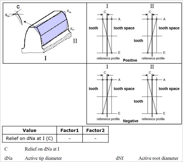
Figure 14 Twist