All signal entities (Actuator, Sensor and, Target) should be already set to simulate FRF.
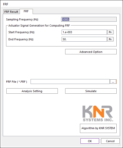
Figure 1 FRF dialog box [FRF tab]
•Sampling Frequency (Hz): User cannot change this value. This value is the Sampling Frequency (Hz) of loaded “*.TARGET” data.
•Actuator Signal Generation for Computing FRF: The Actuator signals (called drive signals) for computing FRF is using a Chirp signal (A sweep function) using following two parameters.
•Start Frequency (Hz): Default value is 0.01 Hz.
•End Frequency (Hz): Default value is 100.0 Hz.
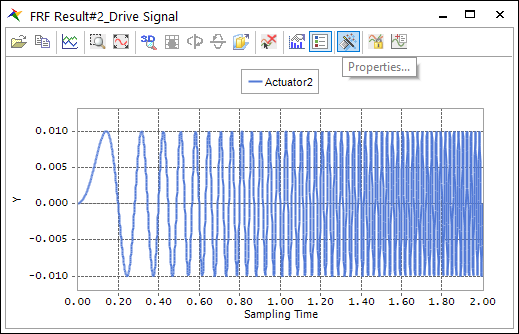
Figure 2 Chirp signals
•Advanced Option: Currently user can change to magnitude data of each Actuator channels. Default magnitude is set to 1.0.
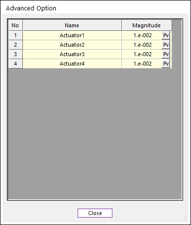
Figure 3 Advanced Option dialog box
•FRF File (*.FRF): Defines a file name and path by clicking ….
•Analysis Setting: Dynamic/Kinematic Analysis dialog is opened. Because, currently TSG is only supported dynamic/kinematic analysis. The End Time and Step should be match on TSG setting.
•End Time data on the Dynamic/Kinematic Anlaysis dialog should be the same with the End Time of “*.TARGET” data.
•Step data on the Dynamic/Kinematic Anlaysis dialog should be set with (End_Time * Sampling_Frequency).
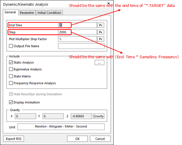
Figure 4 Dynamic/Kinematic Analysis dialog
•Simulate: Computes FRF and generate “*.FRF” file.