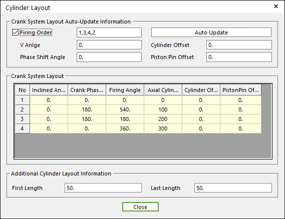
In Cylinder Layout, the user can modify the values to organize the configuration about cylinders and a crank shaft.
Figure 1 Cylinder Layout dialog box
•Firing Order: Defines a sequence of cylinder they are fired.
•V-angle: Defines an angle of between cylinders. It is a value for v-type and horizontal type engine.
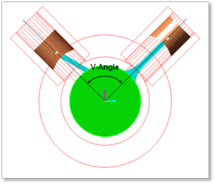
Figure 2 V-angle
•Phase Shift Angel is valid for V-type.
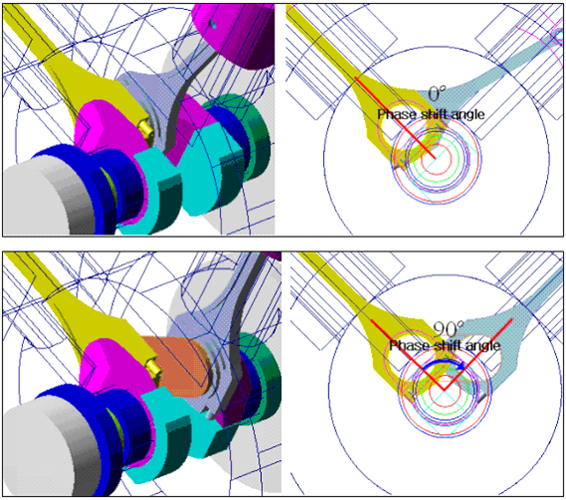
Figure 3 Phase Shift Angle
•Cylinder Offset & Piston Pin Offset
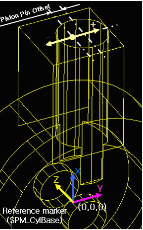
(a) Cylinder offset
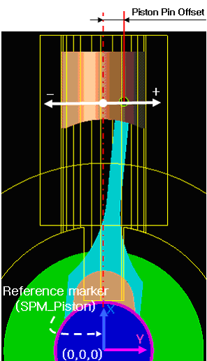
(b) Piston pin offset
Figure 4 Cylinder / Piston pin offset
•Inclined Angle is defined by the v-angle and the cylinder number.
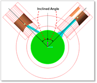
Figure 5 Inclined Angle
•Crank Phase Angle: Enter the angular distance between the slave axis of crank system and the position of the crank pin body. For common engine type, it is automatically calculated from the firing order. If the user wants to give the offset value on a cylinder, modify the crank phase angle on the base of the calculated angle.
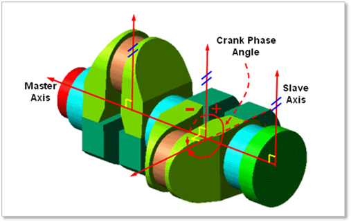
Figure 6 Crank Phase Angle
•Firing Angle: Defines gas force profiles. When a crank shaft is rotated, a gas force acting on a piston is defined by the gas force profile. When the Crank Shaft Angle corresponds with the firing Angle, the concentrated gas force is occurred around Firing Angle (ex. 540 degree, Figure 7). For example, when Crank Shaft Angle is 540dgree, the concentrated gas force is generated in cylinder No 2.
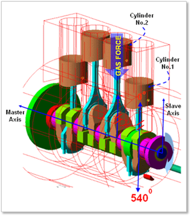
Figure 7 An example of Firing Angle of Cylinder No.2 (CW)
•Axial Cylinder Distance: Enter the axial cylinder distance from the first cylinder.
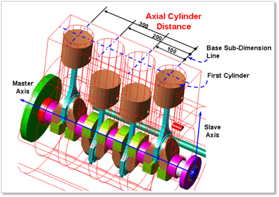
Figure 8 Axial Cylinder Distance
•Additional Cylinder Layout Information
•The first length is the distance between the center point of first main body and first cylinder.
•The last length is the distance between the center point of last main body and last cylinder.
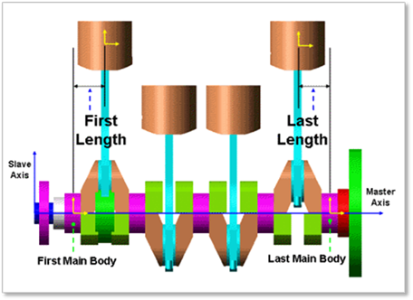
Figure 9 First Length & Last Length