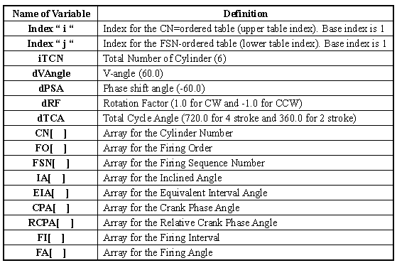
1. Variables Definition
Table 1 Variable definition
2. Input Data
•Engine Type: V-Type
•Rotation Type: CW
•Cycle Type: 4 stroke
•Total Number of Cylinder: 6
•V-Angle: 60 degree
•Phase shift angle: -60 degree
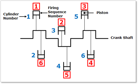
Figure 1 Simplified model of Crank system
3. Calculation Algorithm
•IA[ i ] :(1-2*MOD(CN[ i ],2))*dVAngle/2.0
•EIA[ i ] : (FSN[ i ]-1)*dTCA/iTCN
•CPA[ i ] : MOD((IA[ i ]-EIA[ i ]*dRF),dTCA) : for only V-type odd number cylinder
•CPA[ i ] : MOD((IA[ i-1 ]-EIA[ i-1 ]*dRF)+dPSA),dTCA) : for only V-type even number cylinder
•* CPA[ i ] : MOD((IA[ i ]-EIA[ i ]*dRF),dTCA) : for non V-type engine / for all cylinder
•RCPA[ i ] : MOD(CPA[ i ]-CPA[1], dTCA) : except for the case of “ i=1 “, RCPA[ 1] =0.0
•FI[ j ] : MOD((IA[ j ]-IA[ j-1 ])-(RCPA[ j ]-RCPA[ j-1 ])).360.0) : except for the case of “j=1” , FI[ 1 ]=0.0
•FA[ j ] : FI[ j ] + FA[ j-1 ] : except for the case of “j=1”, FA[ 1 ]=0.0
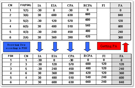
Figure 2 Calculation procedure
If all data is confirmed, special parametric markers and special parametric values are automatically created according to the global data. Each parametric marker represents the global position of each part and control the origin and direction of each part.
The parametric
marker is parameterized by parents-child relationship. For example,
SPM_AssebmlyBase is the parent parametric marker of SPM_CylBase_i.
So, if SPM_AssemblyBase is moved, SPM_CylBase_i is moved together
because the parent marker is moved. In same way, SPM_ShaftPin_i is also
moved.
It can be checked at SPM menu and SPV menu
in Parameter group in the Crank tab.
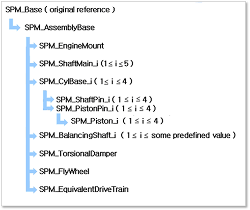
Figure 3 Parameterization of Special Parametric Marker (in case of Straight 4 Cylinder Type)
•SPM_Base: Represents the whole base of crank-system. It cannot be modified.
•SPM_AssemblyBase: Represents the whole control marker of crank-system. If it is moved, the whole crank system is moved.
•SPM_EngineMount: Represents the position of Engine Mount.
•SPM_ShaftMain_i: Represents the position of crankshaft main body.
•SPM_CylBase_i: Represents the position of each cylinder. It is affected by the included angle of cylinder and the axial cylinder distance.
•SPM_ShaftPin_i: Represents the position of crankshaft pin body. It is affected by the included angle, the crank phase angle and, the axial cylinder distance.
•SPM_PistonPin_i: Represents the position of crankshaft main body.
•SPM_Piston_i: Represents the position of piston pin.
•SPM_BalancingShaft_i: Represents the position of balancing shaft.
•SPM_TorisonalDamper: Represents the position of Torsional damper.
•SPM_FlyWheel: Represents the position of fly wheel.
•SPM_EquivalentDriveTrain: Represents the position of EDT.
o Position information of SPM
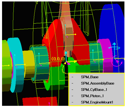
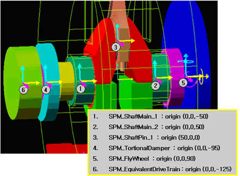
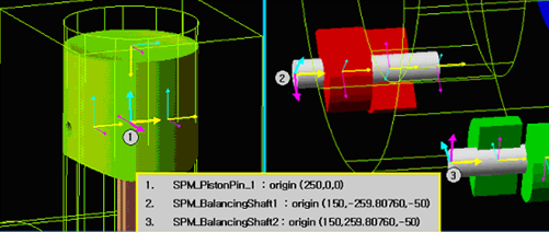
Figure 4 The position information of SPM
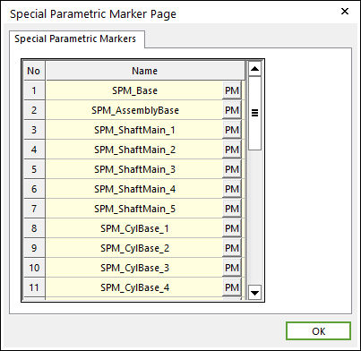
Figure 5 Special Parametric Marker dialog box
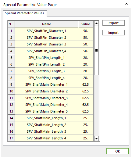
Figure 6 Special Parametric Value dialog box