Practically all control systems that are implemented today are based on computer control.
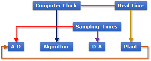
A computer-controlled system can be described schematically as shown in Figure1.
•Outputs from the plant are continuous-time signal and converted into digital signals by analog-to-digital (A-D) converter.
•The conversion process is performed and controlled by selected sampling times.
•The system computer:
•Interprets the converted signals
•Processes the measurements using a control algorithm
•Gives new digital signals.
•The generated signals from the control algorithm are also converted into analog signals for plant input by a digital-analog (D-A) converter.
•The real time clock in the computer synchronizes the events.
Figure 1 Schematic diagram of a computer controlled system
In the simulation of a computer-controlled system, design algorithms of controller and mechanical systems (so-called plants) should be evaluated simultaneously.
•The control algorithm is easily designed by control design application software such as MATLAB/Simulink
•The plant is constructed by mechanical system simulation software such as RecurDyn.
•An interface toolkit such as the RecurDyn/Control is required to communicate between the control system design and mechanical system design software. The schematic diagram of RecurDyn/Control is shown in Figure2.
•RecurDyn simulates the plant model and the control design software simulates the control algorithm in this co-simulation architecture.
•During the co-simulation between RecurDyn and the control system design software, the result outputs from RecurDyn and the control system design tools are passed to each other at a constant sampling time.
•Thus the outputs from RecurDyn are assumed to remain at the same value during the sampling period.
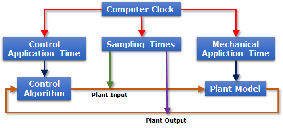
Figure 2 Schematic diagram of RecurDyn/Control