
This page defines characteristic values to contact between two geometry entities. Sprocket, Single Flange, Double Flange, Center Flange, Flat Type, and Roller Guard supported in RecurDyn are using this page.
Figure 1 Single Flange property page [Contact page]
Contact normal force
The contact normal force is obtained by

where, k and c are the stiffness and damping
coefficients which are determined by an experimental method, respectively.  and
and  are a penetration and
time differentiation of the penetration, respectively. The exponents
are a penetration and
time differentiation of the penetration, respectively. The exponents  and
and  generates a non-linear contact
force and the exponent
generates a non-linear contact
force and the exponent  yields an indentation damping effect.
•Characteristic: Defines the contact properties such as the stiffness coefficient, damping coefficient, and friction coefficients. Also, these coefficients can be given as user-defined spline curves.
•Stiffness Coefficient: Specifies a stiffness coefficient for the contact normal force.
•Stiffness Spline: The spline shows the contact normal force for the penetration. For more information, click here.
•Damping Coefficient: Specifies a damping coefficient for the contact normal force.
•Damping Spline: The spline shows the contact normal force for the velocity of penetration. For more information, click here.
•Dynamic Friction Coefficient: Specifies a dynamic friction coefficient for the contact friction force. It has three options.
o Dynamic Friction Coefficient: The constant friction coefficient is applied.
o Friction Force Spline: The spline shows the fiction force for the relative velocity. It is recommended to use the spline that x and y values are defined as positive.
o Friction Coefficient Spline: The spline shows the friction coefficient for the relative velocity.
•More: Specifies some friction coefficients for the contact friction force. Refer to Friction.
•Stiffness and Damping Exponent: Generates a non-linear contact normal force.
•Indentation Exponent: Yields an indentation damping effect. When the penetration is very small, the contact force may be negative due to a negative damping force, which is not realistic. This situation can be overcome by using the indentation exponent greater than one.
•Contact Output File: When this function is checked, RecurDyn creates the contact output file for contact information between sprocket and track links as follows. (Please refer to this option only output the results for track links, they checked at output tap in assembly information). The name of output file will be 'ModelName_ContactName.out'.
|
Col. |
Variables |
Descriptions |
|
1 |
Time (sec) |
Simulation Time |
|
2 |
amount of contact point |
Total number of calculated contact points |
|
3 |
Pos_TX of Sprocket CM |
Position X of Sprocket’s center marker |
|
4 |
Pos_TY of Sprocket CM |
Position Y of Sprocket’s center marker |
|
5 |
Pos_TZ of Sprocket CM |
Position Z of Sprocket’s center marker |
|
6 |
Pos_PSI of Sprocket CM |
Orientation Psi of Sprocket’s center marker |
|
7 |
Pos_THETA of Sprocket CM |
Orientation Theta of Sprocket’s center marker |
|
8 |
Pos_PHI of Sprocket CM |
Orientation Phi of Sprocket’s center marker |
|
9 |
|
The index for contact points |
|
10 |
Track Link ID |
Contacted track link’s ID |
|
11 |
Pos_TX of Track Link CM |
Position X of Track Link’s center marker |
|
12 |
Pos_TY of Track Link CM |
Position Y of Track Link’s center marker |
|
13 |
Pos_TZ of Track Link CM |
Position Z of Track Link’s center marker |
|
14 |
Pos_PSI of Track Link CM |
Orientation Psi of Track Link’s center marker |
|
15 |
Pos_THETA of Track Link CM |
Orientation Theta of Track Link’s center marker |
|
16 |
Pos_PHI of Track Link CM |
Orientation Phi of Track Link’s center marker |
|
17 |
|
The index for contact points |
|
18 |
Global contact position |
Global contact position |
|
19 |
Contact position based on Sprocket |
Contact position based on Sprocket |
|
20 |
Contact position base on Track Link |
Contact position base on Track Link |
|
21 |
Normal force based on Sprocket |
Normal force based on Sprocket |
|
22 |
Friction force based on Sprocket |
Friction force based on Sprocket |
|
23 |
Normal force based on Track Link |
Normal force based on Track Link |
|
24 |
Friction force based on Track Link |
Friction force based on Track Link |
|
25 |
Velocity on Contact Reference Frame |
Normal, Friction velocity based on contact reference frame |
|
26 |
Velocity on Contact Reference Frame (Link Contact Point) |
Velocity of Link Contact Point based on contact reference frame ( |
|
27 |
Angular Velocity on Contact Reference Frame (Link Contact Point) |
Angular Velocity of Link Contact Point on Contact Reference Frame ( |
|
28 |
Velocity on Contact Reference Frame (Sprocket CM) |
Velocity of Link Contact Point based on contact reference frame ( |
|
29 |
Angular Velocity on Contact Reference Frame (Sprocket CM) |
Angular Velocity of Link Contact Point on Contact Reference Frame ( |
|
30 |
Velocity on Contact Reference Frame (Link Pin) |
Velocity of Link Pin on Contact Reference Frame ( |
|
31 |
Angular Velocity on Contact Reference Frame (Link Pin) |
Angular Velocity of Link Pin on Contact Reference Frame ( |
|
32 |
Velocity on Contact Reference Frame (Sprocket Contact Point) |
Velocity of Sprocket Contact Point on Contact Reference Frame ( |
|
33 |
Angular Velocity on Contact Reference Frame (Sprocket Contact Point) |
Angular Velocity of Sprocket Contact Point on Contact Reference Frame ( |
|
34 |
Velocity on Contact Reference Frame (Relative (Link Contact Point –Sprocket Contact Point)) |
Relative Velocity (Link Contact Point – Sprocket Contact Point) on Contact Reference Frame ( |
|
35 |
Velocity on Contact Reference Frame (Relative (Link Pin –Sprocket Contact Point)) |
Relative Velocity (Link Pin CM – Sprocket Contact
Point) on Contact Reference Frame ( |
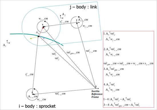
Figure 2 definition of velocity
 )
) )
) )
) )
)

 )
)