A workpiece is constructed with beam elements. The beam elements are the same FFlex/Beam2 element. All nodes of Beam2 have 6 DOFs.
The workpiece does not have a special shape, but it can use a virtual shape for the contact an all functionalities of FFlex.
Coordinate system of Beam Assembly
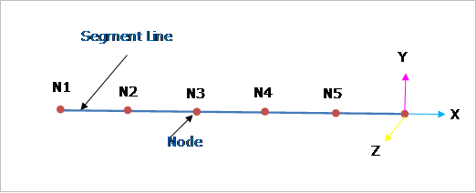
Figure 2 Coordinate system of Beam Belt
The beam segment has nodes and segment lines.
•The segment line connects nodes with the graphic line.
•The center marker of node is located at the point of node and its orientation is dependent on the direction used when the beam segment is created as shown in Figure 2.
•If you apply the plus values in the initial velocity of beam segment, the beam segment moves into the plus direction of the x-axis of the center marker of each node.
•Definition for direction of z-axis, as following:
•The plus direction of the z-axis of an assembly is the plus direction of the z-axis of working plane.
•All the z-axis of node is same in an assembly.
•From the direction of z-axis and x-axis, the direction of y-axis is determined.
Moments of Area of Beam Assembly
(a) Flat Shape
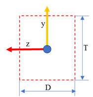
Figure 3 Nodal Masses and Moments of Inertia
•Moments of Inertia
•Flat Shape
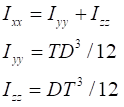
where,
Ixx, Iyy and Izz are the area moment of beam assembly.
D is the depth of beam assembly
(In the default value, D is fixed with 100, independent of the units).
T is the thickness of beam assembly.