The user can define the reference plane for the Working Plane and modifies the property of the grid.
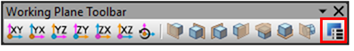
Figure 1 Working Plane Setup icon in the Working Plane Toolbar
Working Plane Setup dialog box
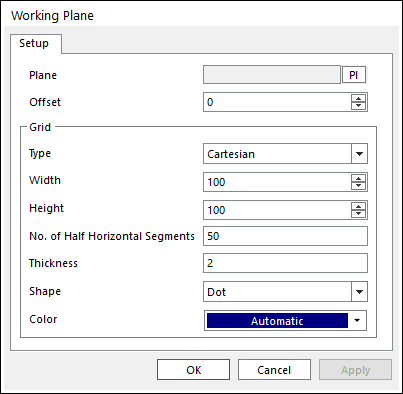
Figure 2 Working Plane dialog box
•Plane: Selects the plane to work using the navigation command. The user can navigate a face of solid or a plane of marker.
•Offset: Defines offset value of the selected plane.
•Grid
•Type: Selects Cartesian or Cylindrical.
•Width: Defines the horizontal distance between grids in the selected plane.
•Height: Defines the vertical distance between grids in the selected plane.
•No. of Half Horizontal Segments
•Thickness: Defines the thickness of a grid in the selected plane.
•Shape: Selects Dot or Line or Cross for the working plane shape.
•Color: Specifies the working plane color from the selected plane.
Step to define Working Plane
1. Click the Working Plane Setup icons in the View Control Toolbar
2. Click PI.
3. Select a plane as Working Plane as shown below. You can specify a Working Plane in a marker or flat face.
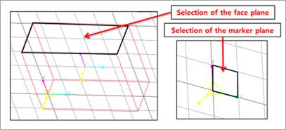
Figure 2 Selection of Working Plane
4. Select Working Plane
5. Click OK.