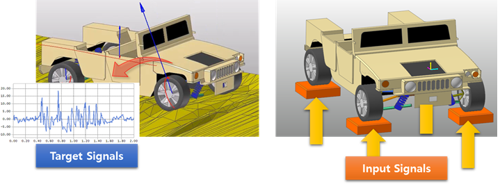
RecurDyn/TSG (Time Signal Generator) generates Input Signals by using the signal processing. After the Target Signals are obtained such as accelerations, velocities, displacements, and so on at the specific locations of a physical model in the experimental test, RecurDyn/TSG can find out Input Signals so that the Target Signals can be matched after simulation. After that, the Input Signals can be applied to Forces or Motions (displacement, velocity, acceleration) as function expressions in the MBD model.
In experimental test, test engineers can measure Experiment Data such as accelerations, forces, angular position and displacements at some location of the structure. However, the measured data can’t be applied directly to the MBD model in RecurDyn because the MBD model can’t be built considering all non-linear properties of physical model. That means that the MBD model is different with the physical model. Therefore, it is needed to calculate the new Input Signals of the MBD model in order to match the measured signals of the physical model. If the Output Signals of MBD are similar to the measured signals after applying the new Input Signal to the MBD model, the MBD Model can guarantee the similar model compared to the physical model.

Figure 1 Target Signals and Input Signals
TSG Terminology
•Target Signals are user-defined signals that we want to reproduce and that has been measured experimentally.
•Response Signals are Output Signals of RecurDyn at the location of the virtual Sensors during iterative simulation. These signals at the end of the process have to match the Target Signals.
•Drive Signals are Input Signals of MBD model at the location of the virtual Actuators.
•Actuator Defines Drive Signal Locations applied to Motion or Force on the Joint or Force elements on a MBD Model.
•Sensor Defines Response Signal Locations to match user-defined Target Signals as a general Expression.

Figure 2 TSG Terminology
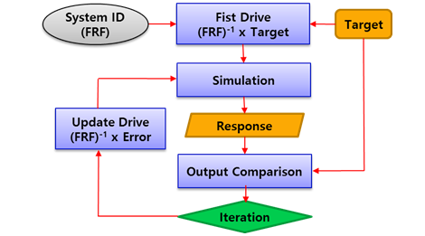
TSG Procedure
1. Set up virtual Actuators & Sensors. This implies that the user needs to define the location, type and direction of the measurement in RecurDyn.
2. Define an association between the sensors and Target Signals.
3. Calculate FRF (Frequency Response Function) after simulation.
4. Correct the drive signal iteratively using the error between Target Signals and Response Signals.

Figure 3 TSG Procedure flowchart