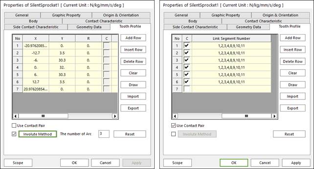
Figure 1 Silent Sprocket property page [Tooth Profile tab]
•X,Y,R: Defines points and radius.
•C, Link Segment Number: If Use Contact Pair option is checked, points for contact with links can be selected and node number of the link for contact can be modified.
•Add Row: Adds a row to the end of the table.
•Insert Row: Inserts a row where the cursor is and move the current and later rows down.
•Delete Row: Deletes the row where the cursor is and move the later rows up.
•Clear: Deletes all rows in the table.
•Draw: All data must be defined with respect to the sprocket tooth marker. You can move points graphically by using the mouse directly.
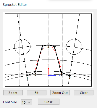
Figure 2 Sprocket Editor dialog box
•Import: Imports the X, Y, and R data pairs from a CSV file or a MAT file or a text file. In the case of the text file, the usage of the comma, the tab, and the space can be the delimiter between the three columns in the file. And when using the Excel file, the user can select the Tab-delimited text file output option or the CSV (Comma-Separated Values) file output option to save the Excel file which can be imported.
•Export: Exports the X, Y, and R data pairs to a CSV file or a MAT file or a text file.
•Use Contact Pair: by dragging the scroll bar to the right side, a user can see hidden data (Link Segment Number) which contact with node number of a silent sprocket respectively.
•Involute Method: If it is checked, the tooth profile can be defined as the involute curve.
•The number of Arc: If Involute Method function is activated, the user can enter the number of arcs. The involute curve of gear tooth is represented by multiple arcs.
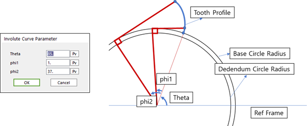
Figure 3 Input parameter & Outline of Involute formulation
•Reset: In order to apply the modification of tooth, this button should be clicked.