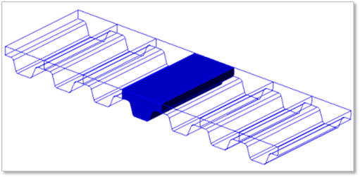
The continuous belt system is modeled by belt segments and a matrix force element. The matrix force is used to connect two segments of the belt system. You must create the one-reference belt segment from all belt segments. (All belt segments are copied.)
•Once the belt segment is created, it is registered as clone body.
•The inertial properties of the assembled belt segments are automatically duplicated to be the same as values of the clone body.
•The belt properties should be defined carefully prior to assembling the belt system.
•The matrix force connecting two belt segments is automatically created when the belt system is assembled.
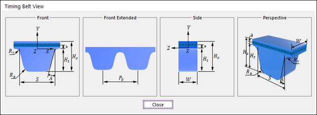
Geometric Timing belt
The geometric information provided by user is used for both the display and the contact force computation in the solver.
|
Pb |
Pitch |
|
W |
Belt Width |
|
a |
Cord Distance |
|
A |
Belt Angle |
|
S |
Tooth Length |
|
Ht |
Tooth Height |
|
Hs |
Nominal Height |
|
Rr |
Tooth Root Radius |
|
Ra |
Tooth Tip Radius |
(b) Dimension information
Figure 1 Timing belt