In the System Component Builder dialog box, the user can specify the component that can be created.
Figure 1 Component icon of the Crank group in the Crank tab
1. Click the Component icon of the Crank group in the Crank tab. The user can see the Crank System Component Builder dialog box.
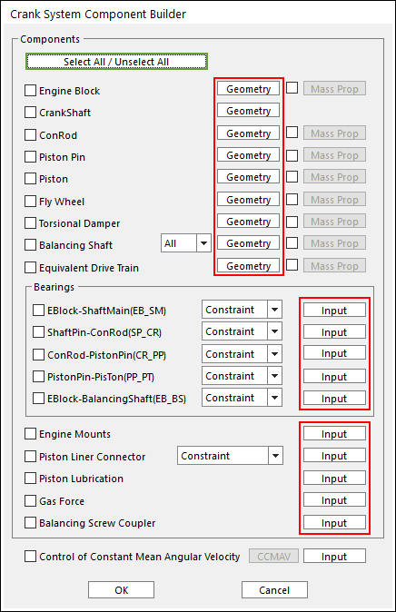
Figure 2 Crank System Component Builder dialog box
• Box in above dialog is
explained in detail in the manual of Geometric Entities including an Engine
Block, a Crank Shaft, Con-rods, Piston Pins,
Pistons, a Fly Wheel, a Torsional Damper, Balancing
Shafts and an Equivalent Drive Train.
Box in above dialog is
explained in detail in the manual of Geometric Entities including an Engine
Block, a Crank Shaft, Con-rods, Piston Pins,
Pistons, a Fly Wheel, a Torsional Damper, Balancing
Shafts and an Equivalent Drive Train.
2. The user can select components, which the user needs to create.
3. For Bearings, there are four types of bearing such as Bushing, EHD, Constraint and Ball type. The Ball type can be selected only for connecting between Eblock-ShaftMain (EB_SM).
4. Engine can be mounted by Bushing Force or Fixed Joint. The mounted type can be defined in Global Data.
5. After checking the check box in above dialog, click Material, and then the user can input information about Center Marker Position, Mass and Inertia Moment of the component the user selected.
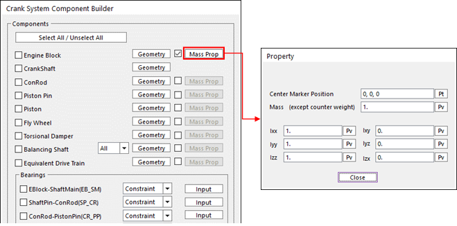
Figure 3 Material Property
6. When all data is confirmed, the checked components are automatically created and updated at database.