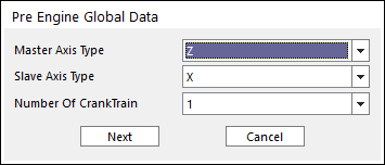
6. Click the Data icon of the Engine group in the Engine tab. You can see Pre Engine Global Data Dialog.
Figure 1 Pre Engine Global Data dialog box
•Master Axis Type: Select the axis which can be the rotating axis of crank shaft.
•Slave Axis Type: Select the axis which can be the cylinder's direction.
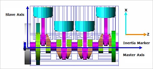
Figure 2 Master & Slave Axis of Crank System
•Number Of Crank Train: Select the number of crank train that can be created. (The maximum number of crank train is 4.)
7. After the pre global data is confirmed, the data is unchangeable. So, if Next is clicked in figure, the warning message is displayed as below figure.
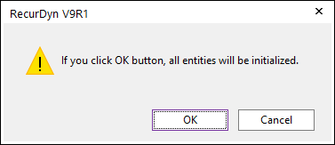
Figure 3 Warning Message
8. After that, Engine Global Data dialog box appears.
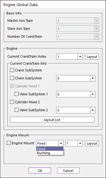
Figure 4 Engine Global Data dialog box
9. In the Basic Info region, the confirmed pre global data is displayed. In the Engine region, construct the engine system as the number of crank train, and define the coordinate of engine system.
•Current Crank Train Index: Selects the current crank train system.
•If the user clicks the Layout in figure, the Crank Train Coordinate System dialog box appears. In this dialog box, the user can confirm and define the position of SPM for the current crank train. There are two kinds of Input Method. One is the X-Y-Z input method. The other is the R-Theta-Z Input method.
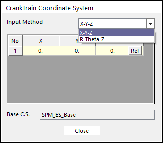
Figure 5 Crank Train Coordinate System dialog box
•If the user clicks Ref in figure, you can confirm the information of SPM which is the reference maker of Current Crank Train such as the name of SPM, the origin of SPM and the orientation of SPM.
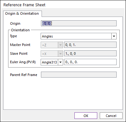
Figure 6 Reference Frame dialog box
10. In the Current Crank Train Info region, select subsystems to construct the engine system and define the number and location.
•Crank SubSystem: Select yes or no for using the crank system.
•Chain SubSystem: Select yes or no for using the crank system and the number of crank system.
•Cylinder Head 1: To construct the valve system, you need a cylinder head at least (default selected). It is made the type of box.
•Valve SubSystem 1: Select yes or no for using the valve subsystem.
•Cylinder Head 2: Make the cylinder head 2. Additionally, if you need the valve system, select the valve system.
•Valve SubSystem 2: Select yes or no for using the valve subsystem.
•If the user clicks Layout List of Current Crank Train Info region in figure, the Layout List dialog box appears as below figure.
In this dialog box,
① The user can confirm and define the position of SPM for the crank, chain, cylinder head and, valve subsystem. There are two kinds of Input method. One is the X-Y-Z input method. The other is the R-Theta-Z Input method.
② Subsystems are imported by clicking Nav. and File. So, the user can navigate the subsystem in the Working Window and open the RecurDyn Subsystem file (*.rdsb)
③ Also, the user can confirm and define the inclined angle, the phase angle, the function of auto positioning(APF) (Only the valve subsystem)
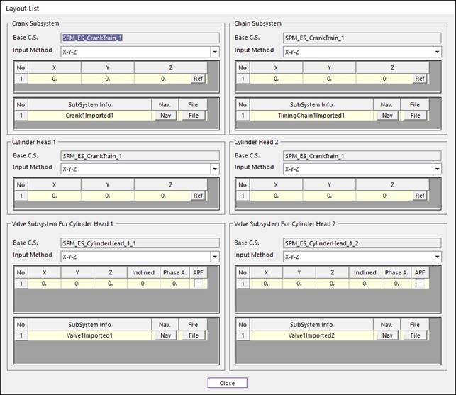
Figure 7 Layout List dialog box
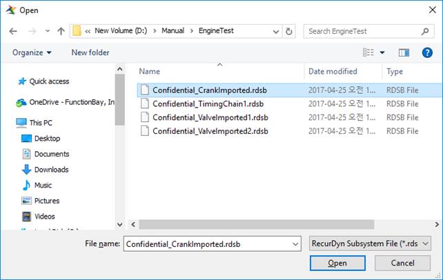
Figure 8 Open the Recurdyn Subsystem File (*.rdsb)
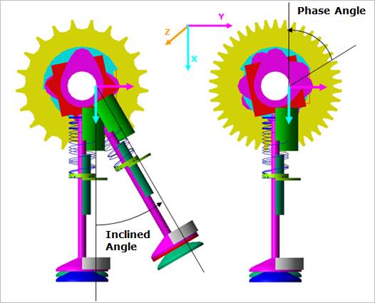
Figure 9 Inclined Angle & Phase Angle
11. In the Engine Mount region,
•Engine Mount: Select yes or no for the connection between the EBlock of crank system and the mother body. The user can select Fixed or Bushing as fixed joint type or bushing type.
•If the user clicks Layout of Engine Mount in figure, the Engine Mount Coordinate System dialog box is opened. In this dialog box, the user can confirm and define the position of SPM of Engine Mount. There are two kinds of Input method. One is the X-Y-Z input method. The other is the R-Theta-Z Input method.
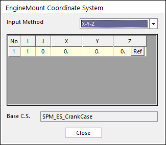
Figure 10 Engine Mount Layout dialog box
•If the user clicks Ref in figure, the user can confirm the information of SPM which is the reference maker of engine mount, such as the name of SPM, the origin of SPM and the orientation of SPM.
12. When all data is confirmed, the checked components are automatically created and updated at the Database.
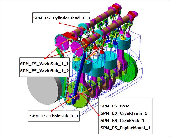
Figure 11 Special Parametric Markers (SPM)