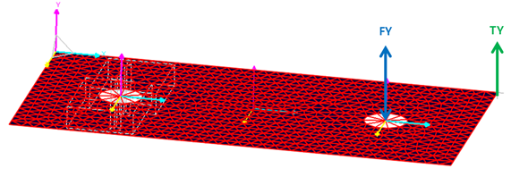

Figure 1 Example mode for FRA
1. Prepare a Model
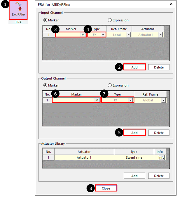
2. Define the input and output by selecting markers in the Excitation Loads for RFlex and/or Rigid Body.

Figure 2 Definition of FRA Excitation Loads
① Click the Exc.RFlex icon of the FRA group in the Flexible tab.
② Click Add in Input Channel group.
③ Click M and then select a marker for input.
④ Select the Type as FX, FY, FZ, TX, TY and TZ.
⑤ Click Add.in Output Channel group
⑥ Click M and then select a marker for output.
⑦ Select the Type as TX, TY, TZ, RX(Roll), RY(Pitch), RZ(Yaw), VX, VY, VZ, WX, WY, WZ, ACCX, ACCY, ACCZ, WDTX, WDTY, WDTZ, TM, VM, WM, ACCM, and WDTM.
⑧ Click OK.
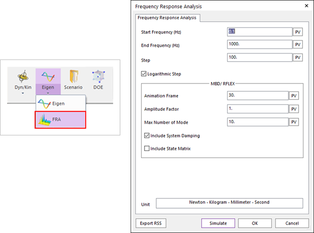
3. Set Start /End Frequency and Step.

Figure 3 Definition of Frequency Response Analysis
4. Draw the result.

Figure 4 Drawing FRA Plot