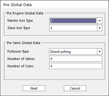
7. Click the Data icon of the Valve group in the Valve tab. The user can see the Pre Global Data Dialog.

Figure 1 Pre Global Data dialog box
•Pre Engine global Data : Defines the Master Axis Type and Slave Axis Type
•Pre Valve Global Data
•Follower Types
o Direct-acting
o Center-Pivoted arm
o End-Pivoted Arm
o Push-rod & Center-Pivoted arm
•Number of Valve and Number of Cam: Defines the number of valve and cam.
8. Previous defined values are the basic information to create the valve system. After these data are confirmed, each value is unchangeable. So, if Next is clicked, the warning message is displayed.
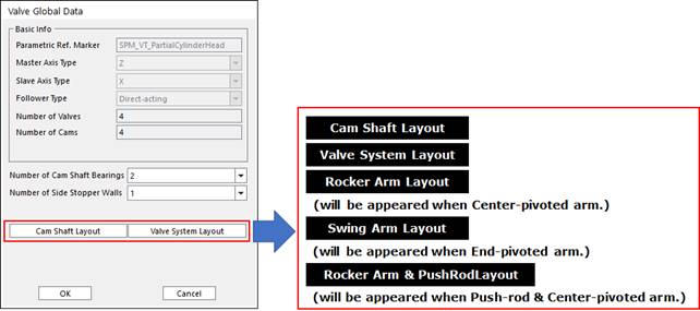
9. After that, the Valve Global Data Dialog is opened.

Figure 2 Valve Global Data dialog box
•The user can define Number of Cam Shaft Bearing and Side Stopper Wall.
10. After setting all parameters, click OK.
11. The user can define the geometric and connection information using the Component Builder.