Step to design the control system
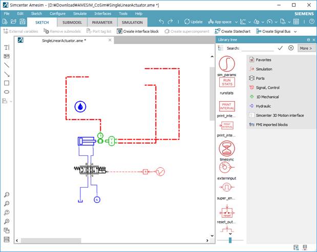
1. In Amesim, open the SingleLinearActuator.ame file.
Figure 1 Amesim dialog box
Create an interface block as following function: “Interfaces > Create interface block…”.

Figure 2 Amesim Interfaces menu
2. Select a type of interface as Functional Mock-up Interface (FMI). And then, set the number of inputs and outputs.
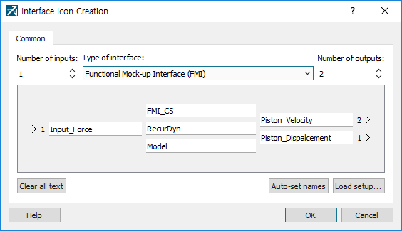
Figure 3 Amesim Interface Icon Creation dialog box
3. Click OK. And then, click Amesim sketch mode and connect the input/output line like blew figure.
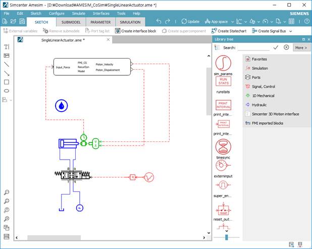
Figure 4 Configuration of the control system
Step to compile the control system
1. Select “Tools > Preferences > Compilation“. And then, change the compiler as following dialog box.

Figure 1 Preferences dialog box
Note: Starting with AMESIM 2019.1, 64-bit GCC Compiler has been developed to enable compilation without Visual Studio.

2. To build the system, click the Parameter mode and Simulation mode.
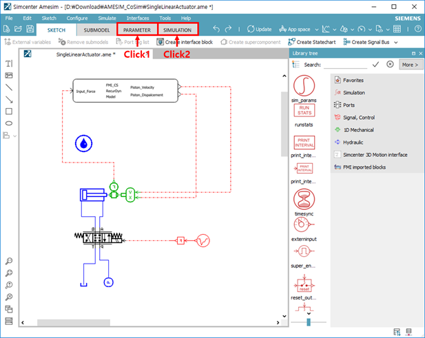
Figure 2 Parameter mode and Simulation mode
3. Select “Interface > FMU Export assistant…”. And then, change the FMU type and version as Co-simulation 2.0.
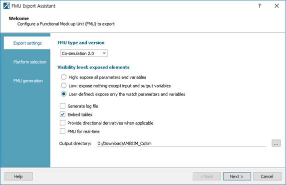
Figure 3 FMU Export Assistant dialog box
4. Click Next and Generate. If there is no problem to compile it, FMU file is generated by Microsoft Visual C++ (64bit) complier.
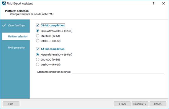
Note: Starting with AMESIM 2019.1, 64-bit GCC Compiler has been developed to enable compilation without Visual Studio.
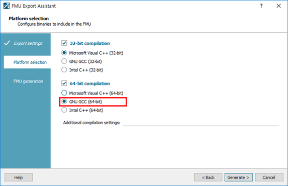
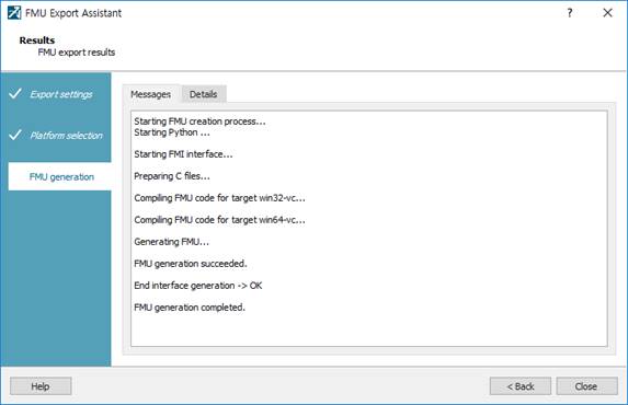
Figure 4 FMU Export Assistant dialog box
Note: If you see a build error message, you should copy Visual C++ variable setting file to Amesim folder.
From: Visual Studio Install Folder\VC\bin\amd64\vcvars64.bat
To: Amesim install Folder\vxxxx\vcvars64.bat
5. Save the Amesim and terminate the Amesim program.