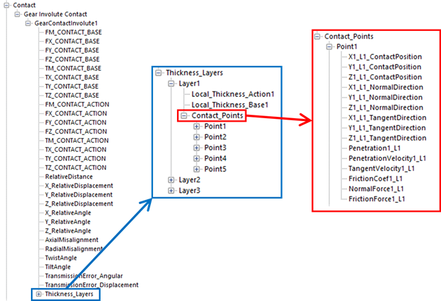
RPLT data of Gear Involute Contact is categorized in layer number and point number. Each layer represents thickness layer in gear rotational axis direction. Each point represents the contact point in profile pair number. Total layer number and total point number in each layer is matched with the number in contact property page. Also, contact forces and torques, and position data for gear pair is plotted. Force and torque are calculated from gear reference frame. Gear reference frame is defined as following rule: y-axis as the displacement vector from base gear center to action gear center, and z-axis as the rotating axis of base gear.
Figure 1 RPLT Data of Gear Involute Contact
•X_RelativeDisplacement: Relative X displacement of action gear center to base gear center in gear ref. frame.
•Y_RelativeDisplacement: Relative Y displacement of action gear center to base gear center in gear ref. frame.
•Z_RelativeDisplacement: Relative Z displacement of action gear center to base gear center in gear ref. frame.
•X_RelativeAngle: Yaw rotation (from Euler 321) of action gear from base gear.
•Y_RelativeAngle: Pitch rotation (from Euler 321) of action gear from base gear.
•Z_RelativeAngle: Roll rotation (from Euler 321) of action gear from base gear.
•AxialMisalignment: Change of axial offset between current and initial action gear position from base gear position.
•RadialMisalignment: Change of distance between base gear and action gear.
•TwistAngle: rotation of action gear from base gear in y* axis (refer to Figure 2)
•TiltAngle: rotation of action gear from base gear in x* axis (refer to Figure 2)

Figure 2 Tilt angle and twist angle
•TransmissionError_Angular: If the gear pair does not make an ideal rotation, it is the value expression how much it is. it is calculated by
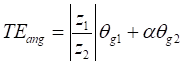
Where,  are the number of teeth for gear1 and
gear2 respectively.
are the number of teeth for gear1 and
gear2 respectively.  is
the rotation angle of gear1 and
is
the rotation angle of gear1 and  is the rotation angle of gear2.
  has ‘1’ in the case of
external gear and it has ‘-1’ in the case of internal gear.
has ‘1’ in the case of
external gear and it has ‘-1’ in the case of internal gear.
•TransmissionError_Displacement: If the gear pair does not make an ideal rotation, it is also the value expression how much it is. This value is widely used in gear analysis. it is calculated by
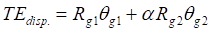
Where,  are the number of base radius for
gear1 and gear2 respectively. Other values are the same as them expressed in
TransmissionError_Angular.
are the number of base radius for
gear1 and gear2 respectively. Other values are the same as them expressed in
TransmissionError_Angular.
Each Layer RPLT structure contains the contact point data which is in that thickness layer.
•Local_Thickness_Action: Thickness position of contact point in action gear center reference frame. Number in the end represents the layer number.
•Local_Thickness_Base: Thickness position of contact point in base gear center reference frame. Number in the end represents the layer number.
Note: Number in the end represents the layer number.
Each Point RPLT structure contains the detailed information about each contact point.
•X_L_ContactPosition: X position of contact point in global ref. frame.
•Y_L_ContactPosition: Y position of contact point in global ref. frame.
•Z_L_ContactPosition: Z position of contact point in global ref. frame.
•X_L_NormalDirection: X component of contact unit normal vector in global ref. frame.
•Y_L_NormalDirection: Y component of contact unit normal vector in global ref. frame.
•Z_L_NormalDirection: Z component of contact unit normal vector in global ref. frame.
•X_L_TangentDirection: X component of contact unit tangent vector in global ref. frame.
•Y_L_TangentDirection: Y component of contact unit tangent vector in global ref. frame.
•Z_L_TangentDirection: Z component of contact unit tangent vector in global ref. frame.
•Penetration_L: Contact penetration. If contact is not occurred, this value is zero.
•PenetrationVelocity_L: Contact penetration velocity (in normal direction).
•TangentVelocity_L: Contact tangent velocity (in tangent direction).
•FrictionCoef1_L: Value of friction coefficient.
•NormalForce_L: Contact normal force.
•FrictionForce_L: Contact friction force.
Note: First number represents the point number, and second number with ‘L’ represents the layer number.