The rotational constraint of the Interpolation element constrains the orientation of the master node to the translational position of the slave nodes. This constraint orients the master node to minimize its angular difference relative to the slave nodes. The goal of the rotational constraint of the Interpolation element is to rotate the master node to follow the rotation of the slave node set. For example, if the slave nodes all orbit around the master node as though they were attached to a rigid body, then the rotational constraint will rotate the master node so that it rotates as though it was also connected to that rigid body. In general, for arbitrary motion of a set of nodes on a flexible body, the nodes might all orbit around the master node, but they will not orbit as though they are attached to a rigid body. Due to the flexibility of the body, they will orbit at slightly different rates. Therefore, the rotational constraint attempts to orient the master node so that it rotates with the average orbital motion of the node set. This is achieved by using a least square minimization of the difference in direction of the slave nodes to the master node in the reference configuration and the current configuration.
For the rotational constraint, the Interpolation element creates a vector from the master node to each slave node in the reference configuration of the nodes of the element.
Figure 3 One vector is created for each slave node in the reference configuration.
These vectors are relative to the master node. If the master node rotates, these vectors rotate with the master node.


At each time step, the constraint computes the current direction vector from the master node to each slave node.


There can be some angular difference between the vector to the slave node in the current configuration and the vector to the slave node in the reference configuration. The reference vector to a slave node rotates with the master node. To find that reference vector in the inertial reference frame, at every time step, the Interpolation element computes

There will generally be some angular difference  between
  and
and  .
.

Figure 4 The vectors and and the angular difference between them. Only 1 slave node is
shown. The master node is red, the slave node is blue.
In general, if the slave nodes all move in some arbitrary direction, it will not be possible to orient the master node so that all reference orientation vectors point directly to each slave node in the current configuration. There will be some difference in direction to some of the nodes. A least square minimization is used to find the orientation of the master node that minimizes the differences in direction to the slave nodes.

Figure 5 The configuration of the master node such that the sum of the square of the angular differences is minimized.
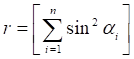
To create a close approximation to the minimization of the
angular differences, a least squares minimization is used. Let  be the sum of the squares of the sines
of the angular differences .
be the sum of the squares of the sines
of the angular differences .
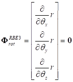
Then is a
minimum when its derivative with respect to the rotation of the master node is
zero. Since there are 3 independent axes around which the master node can
rotate, 3 minimizations are used. This creates 3 equations of constraint for
 :
: