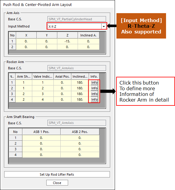
1. Click Rocker Arm & PushRod Layout in the Valve Global Data dialog box. And then the user can see the following dialog box.
•Set up the coordinate system in Rocker Arm’s parts.
Figure 1 Push-rod & Center-pivoted Arm Layout dialog box
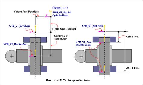
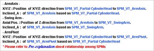
Figure 2 Push-rod & Center-pivoted Arm Layout
2. Click Info in Rocker Arm layout dialog box. And then the user can see the following dialog box.

Figure 3 Push Rod & Center-Pivoted Arm Info dialog box
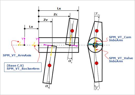
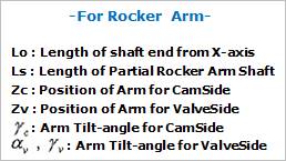
Figure 4 Rocker Arm Layout 1
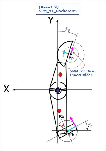
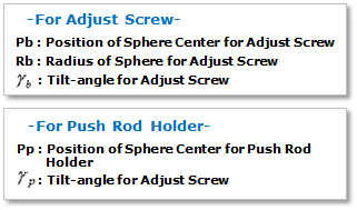
Figure 5 Rocker Arm Layout 2
3. Click Set Up Rod Lifter Parts in the Rocker Arm Layout dialog box. And then you can see the following dialog box.
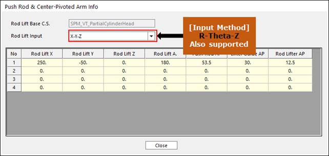
Figure 6 Set Up Rod Lifter Parts dialog box
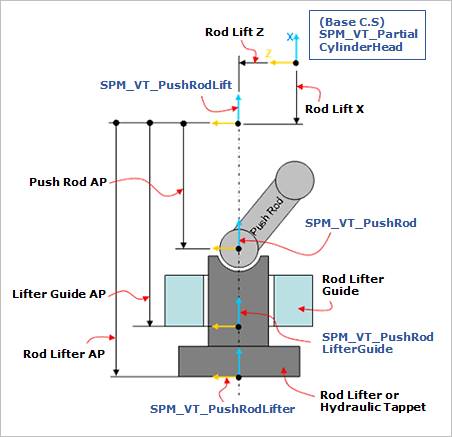
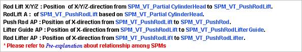
Figure 7 Rod Lifter Parts Layout
4. After setting up all parameters, click Close in the Push-rod & Center-pivoted Arm Layout dialog box.