
Figure 1 Gear Contact Involute property page [Gear Involute Contact page]
•Calculate Contact Pressure: Contact pressure for gear tooth surface is calculated. Contour file is generated. Preview checkbox is activated when calculate contact pressure is checked.
•Contact Pressure Option: Set the number of patches in involute profile and gear tooth thickness for contact pressure calculation and display.

Figure 2 Contact Pressure Option dialog box
•No. of Sections in Profile: Set the number of patches in involute profile.
•No. of Sections in Tip-Relief Curve: Set the number of patches in tip relief curve. If no tip relief area, this number is ignored.
•No. of Slices in Width: Set the number of slices (layers) in thickness direction. This number should be odd number. Note that the number of slices is different with the number of patches (# of patches = # of slices – 1).
Note
If you cannot see the contact pressure result in contour display, increase the number of sections in profile or tip-relief curve. This circumstances can occur when gear material properties are highly stiff, or contact forces are small (It means calculated Hertzian area is small compared to the patch size, so patch size should be decreased accordingly).
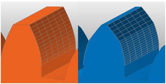
Figure 3 Contact pressure patch preview without tip relief curve (left) and with tip relief curve (right)
•No. of Slices in Width: The number of thickness layers in thickness direction. Gaps between thickness layers are equally divided. This should be odd number to include the mid-surface of gear cross-section. This number is used in contact calculation
•No. of Maximum Output Profile: Defines the number of max involute contact pairs for output. User can define this value from 1 to (Small value among the number of teeth of two gears * 2). This value only affects Force Display and RPLT data about contact points.
•Advanced Option: Tooth flexibility option and contact force averaging method can be set.
•Material Property: Material properties can be set which are used in gear flexibility calculation.
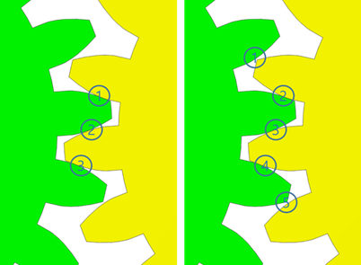
Figure 4 No. of maximum output profile contact pair is 3 and 5.
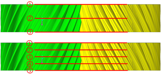
Figure 5 No. of slices in width is 3 and 5.
Advanced Option

Figure 1 Advanced Option dialog box
Tooth Flexibility: Contact stiffness force is calculated with gear tooth flexibility theory.
Note
If tooth flexibility option is activated, stiffness coefficient in characteristic page is not considered in contact analysis. Contact force is calculated only by tooth stiffness factor and material properties.
Also, Averaging Method is disabled when tooth flexibility option is activated. Averaging method is not considered in contact analysis when the tooth flexibility option is used.
•Averaging Method: Accumulated contact forces are averaged with certain factor which is obtained from the number of contact points.
•No Averaging option uses accumulated contact force directly.
•Averaging for Each Pair option calculates partial sum of contact forces for each contact profile pair. And each partial sum is averaged with the number of contact points which are contained in that profile pair.
•Averaging for all Contact Point option counts the total number of contact points and divides all contact forces with the total number.
Material Property

Figure 1. Material Property dialog box
•Synchronize with Body Material Property: Get material properties from body data in RecurDyn or material data provided from KISSsoft. If checked, user-defined input is disabled.