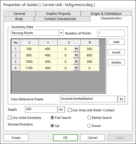
Figure 1 Guide property page [Characteristics page]
The Guide property page is shown in Figure 1. The parameters are explained below.
•Geometry Data: There are 3 type methods to define a guide geometry. Those are Passing Points, Center Points and Radius, and Center Points and Arc Angle.
•Passing Points
o X, Y, Z: Defines a passing point of the guide based on View Reference Frame.
o R: Defines a radius of the guide passing two points.
•Center Points and Radius: Defines geometry data by using center points and radius. For more information, click here.
•Center Points and Arc Angle: Defines geometry data by using center points and arc angle. For more information, click here.
•Number of Points: Shows the number of points.
•Add: Adds a row to the end of the table.
•Insert: Inserts a row where the cursor is and move the current and later rows down.
•Delete: Deletes the row where the cursor is and move the later rows up.
•View Reference Frame: Defines a reference frame for points.
•Depth: Defines the depth of guide.
•Use Only Link Roller Contact: If the guide has narrower width than the pin length of a chain link, its function supports the contact between the Guide with the narrow width and the Roller Link of Roller and Multiplex.
•Use Solid Geometry: The guide shape is shown from surface to solid.
•Full Search: All links are searched for contact.
•Partial Search: Some links are searched for contact in some boundary. It is used to reduce total solving time.
•Normal Direction: Determines the contact direction.