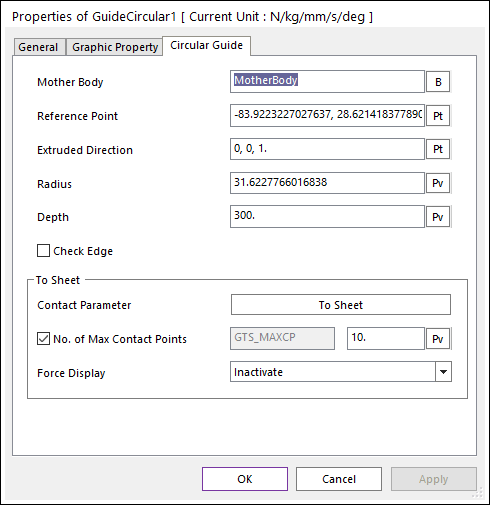
Figure 1 Guide Circular property page [Circular Guide page]
•Mother Body: Defines the name of the guide body including the guide.
•Reference Position: Defines the position of reference marker of the extruded circle geometry.
•Extruded Direction: Defines the z-axis of reference marker of the extruded line geometry.
•Radius: Defines the radius of the extruded line geometry.
•Depth: Defines the depth of the extruded line geometry.
•Check Edge: When the guide radius is smaller than the lengths of a contacted shell element, the contact will not be worked. In this case, if this option is on, the two end sides of the guide are checked in the sheet-to-guide contact. The contact geometry of the guide is represented as two spheres.
•Contact Parameter: Allows the user to modify contact parameters by clicking To Sheet. In this dialog box, the user can modify the contact parameters of contact forces applied between the sheet and the guide. Refer to the Contact Formulus for MTT3D.
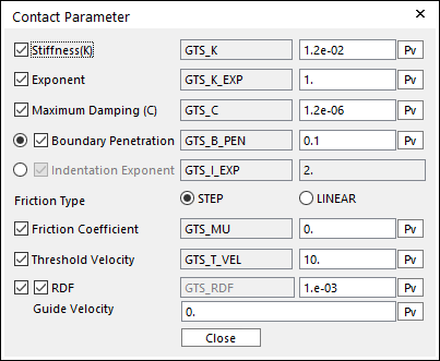
Figure 2 Contact Parameter dialog box
•No. of Max Contact Points: Defines the number of max contact point for output. User can define this value from 1 to 5000. This value only affects Force Display and RPLT data about the contact points. The default value is 10.
•Force Display: Graphically displays the all contact force vectors (the sum of the normal and tangential contact force) at each contact point up to the “No. of Max Contact Point”.