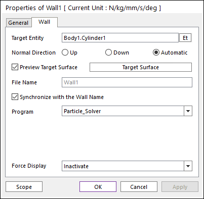
The user can modify the properties of wall in the following dialog box.

Figure 1 Wall property page
•Target Entity: Displays the selected geometry or body.
•Normal Direction: Defines the contact side of the wall.
•Whether or not an option is supported is depending on the particle solver.
•Only the Normal Directions supported by the particle solver will be shown.
•As selecting “Up” or “Down” or “Automatic”, the user can change the contact side of wall.
•Preview Target Surface: If it is checked, the user can visually verify which side is the contact side if Up or Down is selected. The vectors in the Working Window point to the side on which the particles will be able to make contact. The Automatic Normal Direction indicates that the particle solver will use its own algorithm to determine the contact side. Please see the particle solver’s documentation to determine the meaning of this selection.
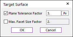
•Target Surface: Sets the mesh size of wall.

Figure 2 Target Surface dialog box
•Plane Tolerance Factor: Specifies the surface tolerance factor as a value from 0 to 10. A smaller value produces a more refined patch. To see more information, click here.
•Max. Facet Size Factor: Specifies the max.facet size factor as a value from 0 to 10. This value controls the maximum size of triangular patch length. To see more information, click here.
•File Name: Defines the name of the file to be exported by the *.obj or *.stl format.
•Synchronize with the Wall Name: If this option is checked, File Name will be the same as the wall name. If it is unchecked, the user can input an arbitrary name into the File Name text field..
•Program: The connected particle solver is shown. The user can choose to use this wall for a different particle solver.
•Force Display: Graphically displays the resultant force vector on the view window.