This page selects nodes to output calculated values. Sheet Shell supported in RecurDyn/MTT3D is using this page.
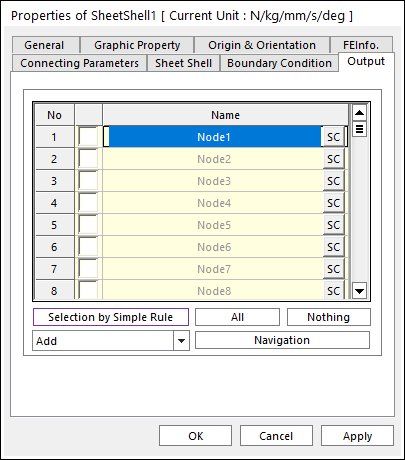
Figure 1 Sheet shell property page [Output page]
•Output: The outputs of selected nodes are shown in Scope and Plot.
•No: Shows the index of nodes.
•Check Option: If this option is checked, outputs are plotted.
•Name: Defines the name of nodes belongs to the sheet shell.
•SC: Determines Scope of each node.
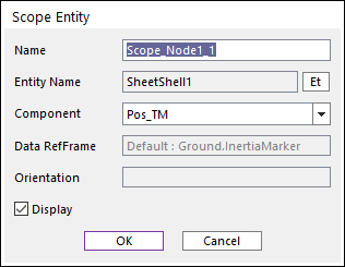
Figure 2 Scope Entity dialog box
o Name: Defines the name of the Scope
o Entity Name: Defines the name of specified node.
o Component: Selects the component of results of the specified node.
o Orientation: Defines the reference frame. The component is projected in the specified reference frame.
o Display: If the user checks this option, the window of Scope is shown.
•Selection by Simple Rule: Allows the user to open the Selection dialog box to support a simple rule selecting many sheet bodies at the same time. For more information, click here.
•All/Nothing: The check boxes of all nodes in the list are activated or deactivated.
•Add + Navigation: If the user selects the Add option and clicks the navigation button, the user can select nodes from the screen and an output is applied on the nodes.
•Remove + Navigation: If the user selects the Remove option and clicks the navigation button, the user can select nodes from the screen and an output is not applied on the nodes.
•Add or Remove + Navigation: If the user selects the Add or Remove option and clicks the navigation button, the user can select nodes from the screen and a boundary condition is applied or not on the nodes.
•Orientation Reference Frame: If the user selects Node option, then the orientation reference frame of the Boundary Condition is set with each node. If the user selects Inertia Marker, then the orientation reference frame of the Boundary Condition is set with Ground.Inertia Marker of the current system. Default is Node.