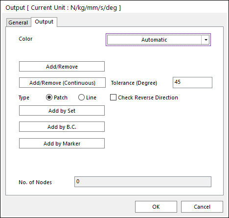
Figure 1 Output dialog box
•Add/Remove: Selects nodes to add or remove for the output nodes.
•Add/Remove (Continuous): Select a patch or line to add or remove continuously with its own patch or line continuity in angle tolerance for an output.
•Tolerance (Degree): Defines an angle tolerance to check patch or line continuity.
•Check Reverse Direction: If this option is checked, nodes are selected regardless to direction of patches or lines in the angle tolerance.
•Type Patch: Select a patch then continuously connected patches are added, and the nodes of the patches are selected.
•Type Line: Select a line then continuously connected lines are added, and the nodes of the lines are selected.
•Add by Set: Selects a set which can be available an element set, a patch set, or a node set for the output nodes. The output nodes are defining all the nodes of the selected set.
•Add by B.C: Selects a boundary condition for the output nodes. The output nodes are defined by all nodes of the select BC. In the case of RFlex body, this option is not supported.
•Add by Marker: Select a maker for the output nodes. The output node is defined as the nearest node of the selected marker.
•Node: If the Automatic Outputs for Marker option in Flexibility Setting is checked, the output is defined automatically. For more information, click here.
•No. of Nodes: Shows the number of nodes in the output.