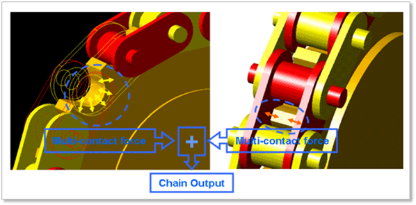
A contact force of a link and a bushing force (chain tension) can be outputted in Plot. The Chain output is summation value of multi-contact force between a sprocket and a chain-link.
Figure 1 Chain output
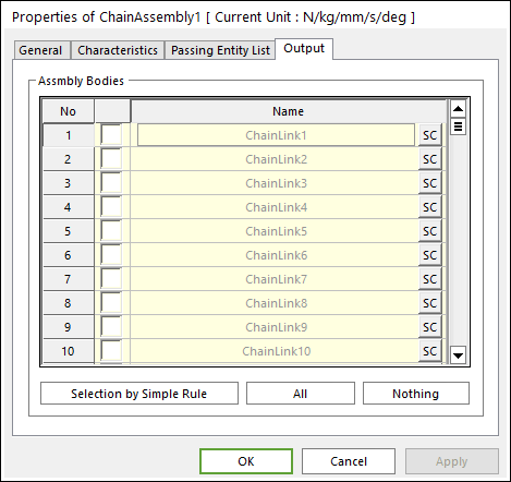
Figure 2 Assembly property page [Output page]
•Output: The outputs of selected links are shown in Scope and Plot.
•No: Shows the index of links.
•Check Option: If this option is checked, outputs are plotted.
•Name: Defines the name of belt bodies belongs to the link.
•SC: Determines Scope of each belt body.
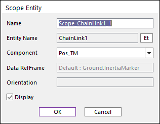
Figure 3 Scope Entity dialog box
o Name: Defines the name of the Scope
o Entity Name: Defines the name of specified link.
o Component: Selects the component of results of the specified link. The contact and elastic forces in the belt body reference frame are included.
o Orientation: Defines the reference frame. The component is projected in the specified reference frame.
o Display: If the user checks this option, the window of Scope is shown.
•Selection by Simple Rule: Allows the user to open the Selection dialog box to support a simple rule selecting many sheet bodies at the same time. For more information, click here.
•All/Nothing: The check boxes of all links in the list are activated or deactivated.