To add output data for the sheet body to the rplt file, check the corresponding sheet body on the page below. The type of data coming out of each sheet body can be found here.
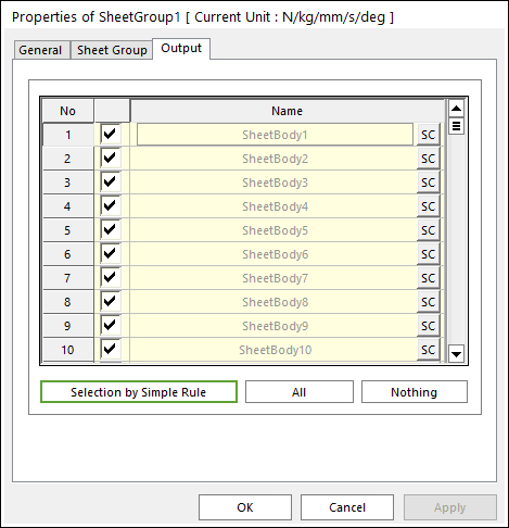
Figure 1 Sheet Group property page [Output page]
•Output: The outputs of selected sheet bodies are shown in Scope and Plot.
•No: Shows the Index of sheet bodies.
•Check Option: If this option is checked, outputs are plotted.
•Name: Defines the name of sheet bodies belongs to a sheet group.
•SC: Determines Scope of each sheet body.
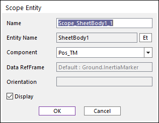
Figure 2 Scope Entity dialog box
o Name: Defines the name of Scope.
o Entity Name: Shows the name of specified sheet body.
o Component: Selects the component of results of the specified sheet body. The contact and nodal force which are measured in the nodal reference frame are included.
o Orientation: Defines the reference frame. The component is projected in the specified reference frame.
o Display: If the user checks this option, the window of Scope is shown.
•Selection by Simple Rule: Allows the user to open the Selection Dialog to support a simple rule selecting many sheet bodies at the same time. For more information, click here.
•All/Nothing: The check boxes of all sheet bodies in the list are activated or deactivated.