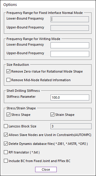
User can change several options related to generating a RFI.
Figure 1 Options dialog box
•Frequency Range of Fixed Interface Normal Mode: If the number of interface node is one or more than one, then this frequency range can be set. The default value is blank.
•Frequency Range for Writing Mode: User can set a frequency range. If user set the frequency range, then the frequency of all written modes must be greater than low-bound frequency and must be lower than upper-bound frequency. The default value is blank.
•Size Reduction: The size of output RFI file can be reduced with these options. For more information, click here.
•Shell Drilling Stiffness: This parameter is needed to set the normal rotational stiffness for shell type elements of Dynamis. And this is similar to “K6ROT” parameter of Nastran. A value between 1.0 and 100.0 is recommended. The default value is 100.0. If user wants to get a more stiffen on the normal rotational stiffness, set a value more than 100.0
•Stress/Strain Shape: This option supports to add stress and/or strain shapes to the generated RFI file. Default is checked.
•Stress shape: The stress shapes should be included in the RFI file.
•Strain shape: The strain shapes should be included in the RFI file.
•Lanczos Block Size: User can change the lanczos block size of an eigen solver of the Dynamis. When an eigen solver error occurred with following message on the LOG file, then user can try with another blocksize. (The default is 3. A bigger blocksize would be better.)
|
Error(20099):Eigenvalue Analysis |
•Allows Slave Nodes are Used in Constraint (AUTOMPC): If this option is used, then the Modal or CMS analysis is available when some slave nodes are used in the two or more RBEs (Rigid body elements) like as Figure 14.
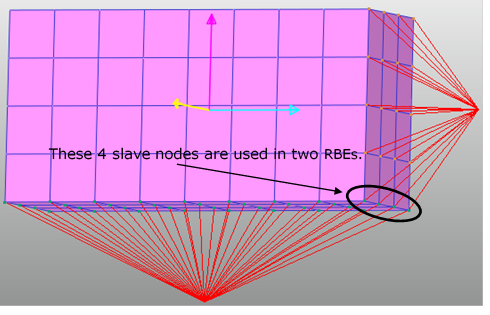
Figure 2 Sharing slave nodes in multi-point constraints
•Delete Dynamis database files (*.DB1, *.MSTR, *OP2): If this option is checked, the Dynamis database files are automatically removed.
•RFI translator (*.txt): If this option is checked, Dynamis makes a debugging text file(*.txt) after generating the RFI file. All data of *.txt files are translated from the RFI file. If the total number of nodes is greater than 10,000, the information about nodes, elements, mode shapes, stress shapes, and strain shapes will not be written in the debugging text files.
•Include BC from Fixed Joint and Flex BC: When Select Flexible Body is used in Mesh Data Type and this option is selected, then all connected nodes with Fixed Joint and all related nodes with FFlex/BC are defined to BC for the RFlexGen Solver. Default is unchecked.
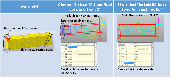
Figure 3 An effect of the “Include BC from Fixed Joint and Flex BC” option
Note
Shell9 and Solid26 elements are not supported in RFlexGen. So, if the user sets mid nodes to the BC, RecurDyn give a waring message as bellows.
"Warning: Mid-node cannot be included to the Interface Node or the BC of the RFlexGen. The selected Mid-Nodes are automatically ignored in the RFlexGen."