Lets’ consider the following sample problem:
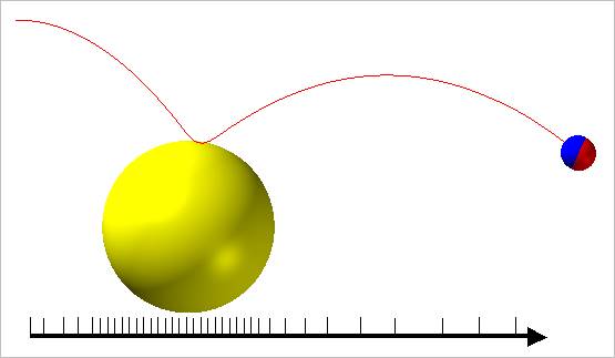
The yellow & the blue ball are fixed on ground. When the red ball is thrown with an initial velocity, the red ball should be contacted with the yellow ball and go through the blue ball as near as possible. Figure 1 shows the optimization result of AutoDesign.
In general, multi-body dynamics solver uses variable step algorithm. In this problem, DAE solver reduces the red ball goes through the yellow ball automatically in order to solve contact problem. Then, it will increase the time steps because it has no kinematical constraints. In Figure 1, ticks represent the time steps in DAE solver. How can you measure the minimum distance between the red ball center and the blue ball center? Maybe, you will define the minimum distance two Marks defined at those ball-centers for the analysis. How about the consistency of distance evaluation?

Figure 1 An optimum trace of red ball center
If design variables are changed, dynamics solver resolves the changed system sequentially. Then, the time steps will be different in all those analysis cases. This inconsistency gives another numerical noise for the minimum distance evaluation. Sometimes, this noise makes the convergence of optimization process to be difficult. Thus, in order to reduce the effect of this typed numerical noise, you had better reduce the time interval by increasing the number steps in Analysis Setting. When one cannot increase the number of time steps, he had better reformulate the design model. In order to reduce the time interval, one can make a dummy rigid wall at the blue ball position. Then, he defines the contact between the red ball and the rigid wall. This approach can reduce the time interval near to the wall. Hence, the minimum distance evaluation between two Marks (red ball and blue ball) has less noise.