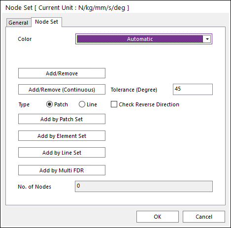
Figure 1 Node Set dialog box
•Color: Select a color to the node set.
•Add/Remove: Select nodes to add or remove for a node set.
•Add/Remove (Continuous): Select a patch or line to add or remove continuously with its own patch or line continuity in the angle tolerance for a node set.
•Tolerance (Degree): Defines an angle tolerance to check patch or line continuity.
•Check Reverse Direction: If this option is checked, nodes are selected regardless to direction of patches or lines in the angle tolerance.
•Type Patch: Select a patch then continuously connected patches are added, and the nodes of the patches are selected.
•Type Line: Select a line then continuously connected lines are added, and the nodes of the lines are selected.
•Add by Patch Set: Select a patch set to add to a node set. The node set defines all nodes of the selected patch set.
•Add by Element Set: Select an element set to add to a node set. The node set defines all nodes of the selected element set.
•Add by Line Set: Select a line set to add to a node set. The node set defines all nodes of the selected line set.
•Add by Multi FDR: Select multi FDR element to add to a node set. The node set defines all master node of the selected FDR element.
•No. of Nodes: Show the number of nodes included in the node set.