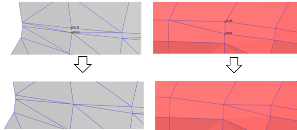
This function combines two nodes and make one node. The related elements are modified. Shell3 elements are deleted and Shell4 elements are converted to shell3 elements.

Figure 1 Example for Node Merge

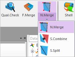
Figure 2 Node Merge icon of the Mesher group in the Mesher tab

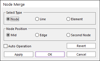
Figure 3 Node Merge dialog box
•Select Type
•Node: Select two nodes. Two nodes are merged.
•Line: Select one line. Two nodes of the line are merged.
•Element: Select one element. The two nodes of the shortest line of the element are merged.
•Node Position
•Mid: The final node is on the middle point of the selected two nodes.

Figure 4 Mid Node Merge (Node, Line, Element from left to right)
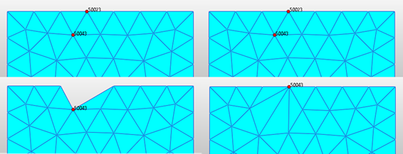
•Edge: If one of the two nodes is on the edge, the final node are on the node position of the edge.

Figure 5 Edge Node Merge (Node, Line, Element from left to right)
•Second Node: The final node is on the selected second node.

Figure 6 Second Node Merge
•Auto Operation
•If the entity (nodes, line or element) are selected than the merge function is applied instantly.
•Revert
•All modification is canceled. It changes to the final mesh result.