The user can work shell operation for one geometric entity by the following procedure.
•Solid, WithDialog
•Solid: Selects a solid geometry.
•WithDialog: Shell Operation dialog box appears, and then selects faces. The shell operation works by clicking OK in the Shell Operation dialog box.
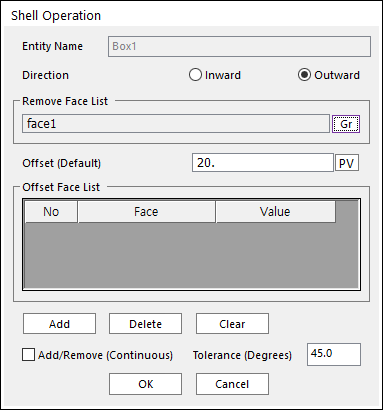
Figure 1 Shell Operation dialog box
o Entity Name: Shows the name of the selected entity.
o Direction: Specifies the direction of the offset as Inward or Outward.
o Remove Face List: Shows the list of faces to remove.
o Offset (Default): Faces excluding Remove Face List faces are offset with this value.
o Offset Face List: Shows the list of faces for the offset. These specify offset values. These faces are offset with their offset values different from the default offset value.
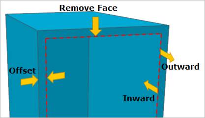
Figure 2 Shell Information
o Add: Selects faces with shell applied. After finishing operation of selecting multi-faces, the row is added for the selected faces.
o Delete: Deletes the selected row by the mouse cursor and move the lower rows up.
o Clear: Clears rows
o Add/Remove (Continuous): When using Add, if this option is checked, the connected faces within the degrees are selected together.
o Tolerance (Degrees): The angle of between the connected two faces.