With FFlex line sets and patch sets, the user can imprint edges on faces of a geometric entity by the following procedure.
•Solid(Sheet), Line/Patch Set, WithDialog
•Solid(Sheet): Selects a solid or surface geometry to create edges on them.
•Line/Patch Set: Selects a line set or patch set to be projected.
o Line Set: Line set is projected to the faces and imprint the edges on the faces.
o Patch Set: The outline of the patch set is projected to the faces and imprint the edges on the faces.
•WithDialog: Sets the direction to be projected. The imprint curves are created by clicking OK in the Imprint Line dialog box.
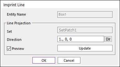
Figure 1 Imprint Line dialog box
o Entity Name: Shows the name of the selected entity.
o Set: Shows the name of selected line set or patch set.
o Direction: Select a direction to project the selected curve.
o Direction: Select a direction to project the selected set.
o Preview: Previews the curve to be projected on Working Window.
o Update: Updates the preview.

Figure 2 Example of Imprint Edge with Line Set

Figure 3 Example of Imprint Edge with Patch Set