Figure 1 Liner icon of the Crank Connector group in the Crank tab
1. Click the Liner icon of the Crank Connector group in the Crank tab. The user can see the Crank Component Liner Connector – Line Connector dialog box.
2. The user can choose the following types in Component Type and select the position where the constraint bearing is created in Component Index.
•Constraint
•Cylinder Contact
•Surface Contact
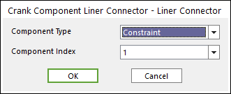
Figure 2 Crank Component Liner Connector – Liner Connector dialog box
3. Click OK.