The user can create a marker by the following procedure.
•Point
•Point: Selects a point to define a position of the marker. The orientation of marker is same with the working plane.
•Point, Point
•Point: Selects a first point to define a position of the marker.
•Point: Selects a second point to define a position of the marker. The marker is created at the center position between two points.
•Point, Direction, Direction
•Point: Selects a point to define a position of the marker.
•Direction: Defines a direction of Z-axis of the marker.
•Direction: Defines a direction of X-axis of the marker.
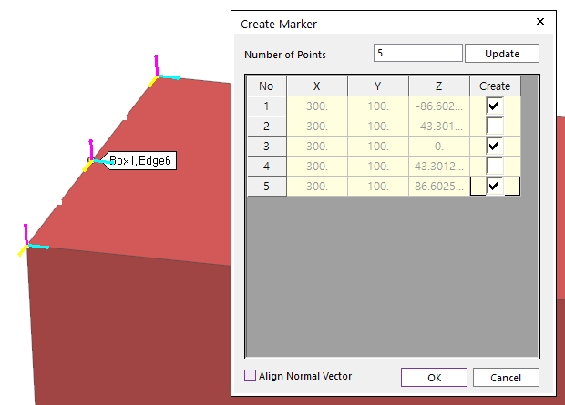
•Curve, WithDialog
Figure 1 Preview for Create Marker
•Curve: Selects a curve. And then, the N division points of the selected curve are displayed with the Create Marker dialog box.
•WithDialog: Selects points to create markers in Create Marker dialog box. And then the markers are created with clicking OK.
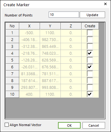
Figure 2 Create Marker dialog box
o Number of Points: Inputs the value for division and clicks Update.
o Create: Checks the check boxes in the Create column and clicks OK.
o Align Normal Vector: If this option is checked, in order to make the Z axis of generating markers align to the normal direction of the selected curve, the orientation of the makers will be changed.
•Solid(Surface, Curve), Solid(Surface, Curve), Predefined Point
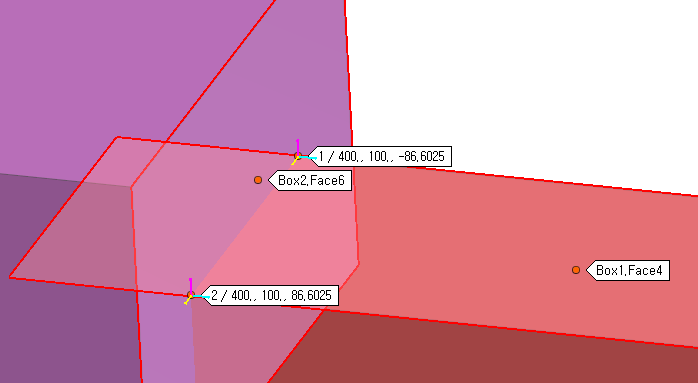
Figure 3 Preview for Predefined Points
•Solid(Surface, Curve): Select a solid, surface, or curve geometry to find intersection points.
•Solid(Surface, Curve): Select a solid, surface, or curve geometry to find intersection points. And then the user can see intersection points between two geometries on Working Window.
•Predefined Point: Select a point among the displayed intersection points on Working Window.