
The example model is 2D rectangular model. The model meshed based on shell 63 element with Element edge length option. Shell 63 element has Real Constant with thickness and the value are same as 0.05 for all. Furthermore, use material property like as steel and boundary condition to fix all degree of freedom impose at all left side node.
Figure 1 Target model
1. Select Mechanical APDL Product Launcher on the popup menu and specify working directory and job name.
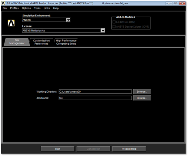
Figure 2 Interactive dialog box
2. Select Structural on the Preferences for GUI filtering
•Preferences for GUI filtering
•Preferences > Structural
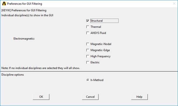
Figure 3 Preference for GUI filtering
3. Select Element Type, Real Constants
•Element type
•Preprocessor > Element Type > Add/Edit/Delete > Add… > Shell 63 > OK > Close
•Enter Real Constants
•Preprocessor > Real Constants > Add/Edit/Delete > Add > OK
•Set shell thicknesses I, J, K, L as 0.05
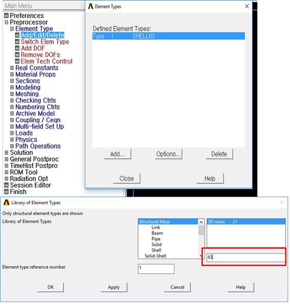
Figure 4 Real constant for shell element
3-1. Set Thickness
•Thickness
•Thickness is important parameter for shell element. Ansys do not support
Real Constant for some shell element.
At the time, thickness can be define
using shell section.
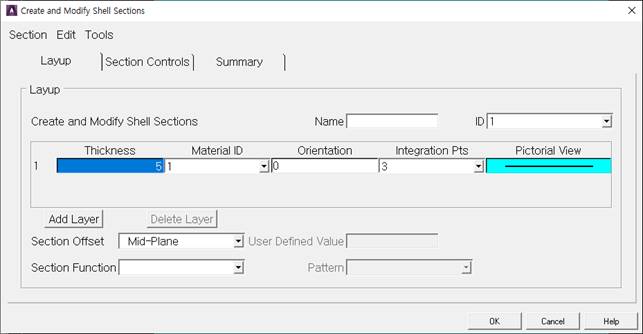
Figure 5 Create Sections for Shell Element
4. Enter Material property
•Material property
•Preprocessor > Material Props > Material Models > Structural > Linear > Elastic > Isotropic > Specify material number as 1 > OK
•Fill in the Young’s modulus(70e9N/m2), Possion ratio(0.33), density(2710kg/m3) > OK
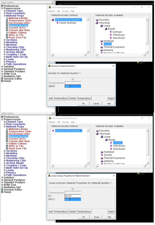
Figure 6 Material Property
5. Create rectangular geometric entity
•Create Rectangle by Dimensions
•Preprocessor > Modeling > Create > Areas > Rectangle > By Dimensions > OK
•Fill the x1, x2, y1, & y2 as 0.0, 0.0, 1.0, & 1.0 > OK

Figure 7 Rectangle by Dimensions
6. Create area meshing using Mesh Tools
•Use line set to define element edge length.
•Preprocessor > Meshing > MeshTool > Size Controls > Lines > Pick All > OK > SIZE element edge length(0.1) > OK
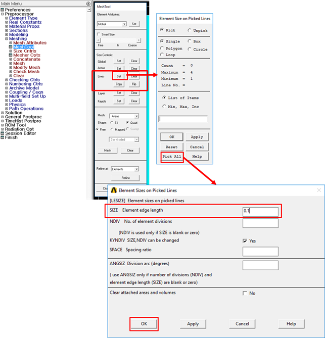
Figure 8 Line set with Element edge length
•Mesh model
•Mesh Tool > Mesh > Select model > OK
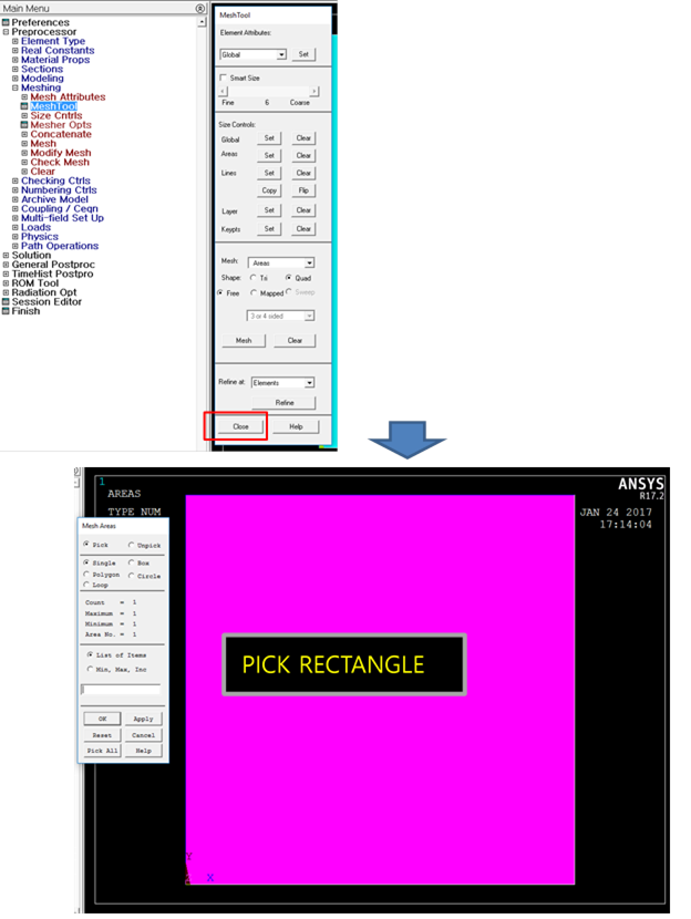
Figure 9 Meshed Rectangular geometric entity
7. Impose Boundary Conditions on nodes
•Apply at node
•Fix all degree of freedom of left side node
•Solution > Loads > Define Loads > Apply > Structural Displacement > On Nodes > Box > drag the window > OK > All DOF > OK
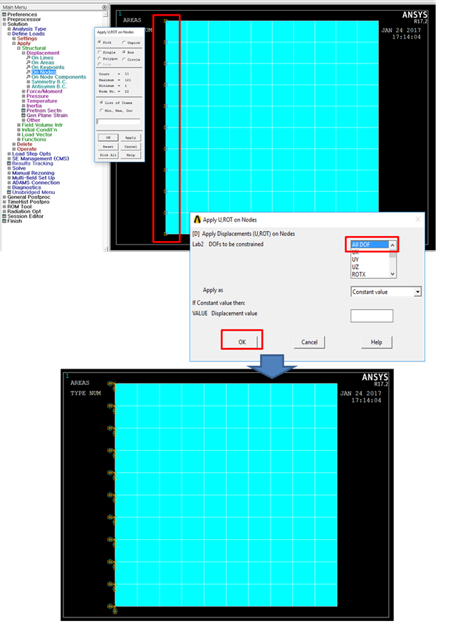
Figure 10 Boundary condition
8. Create output files
•Create *.mp file
•Ansys Command Prompt > ‘mpwrite’
•Create *.emat file
•Ansys Command Prompt > ematwrite, yes’
9. Perform modal analysis
•Set Analysis Type
•Solution > Analysis Type > New Analysis > Modal
•Set Analysis Options
•Solution > Analysis Type > Analysis Options
o Determine the Number of modes to extract and check lumped mass option
o You can also define Start and End frequency
•Perform analysis
•Solution > Solve > Current LS > Finish
10. Check created files
•Created files were stored in working directory
•file.rst
•file.mp
•file.emat