
Figure 1 Target model
1. Run I-DEAS and create model.
•Move to Master Modeler.
•Create a geometric entity.
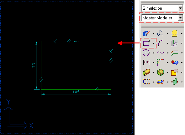
Figure 2 Creation of line

Figure 3 Define surface
2. Define FE model.
•Move to Meshing.
•Define Element
•Select Define shell mesh.
You can define mesh about plate model in ‘Define mesh’ window. That is, you can change element type, element length and etc.
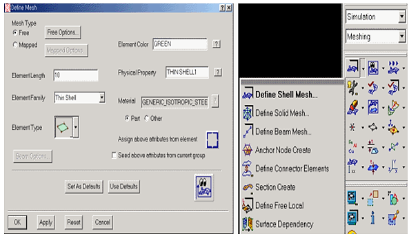
Figure 4 Defining mesh
3. Make a FE entity
•Choose meshing method
•Generate node and element
After choosing the method, select the part and enter. Then you can see the node and element numbers which are generated (Result information) in the top left side on the working window
•Click Yes
If you don’t want to auto mesh, then you can make a node wherever you want and can also generate element with this node
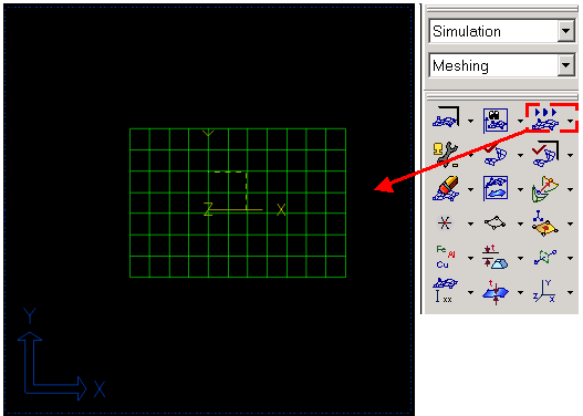
Figure 5 Mesh geometry
4. Define DOF set
•Move to Boundary Conditions
•Create boundary set
Select nodes that will be constrained by applied by a force in the flexible body.

Figure 6 Boundary condition
5. Run program file
•Move to Model Solution.
•Run program file, 'RecurDyn_fem.prg'
After you choose the program file, click OK.
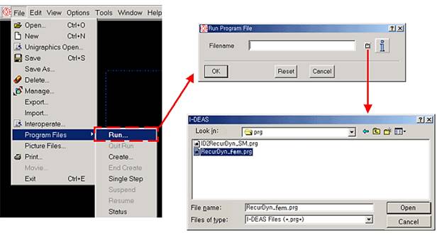
Figure 8 Read program file
•Enter mode number.
Enter number of modes to extract in I-DEAS Prompt window.

Figure 9 Input mode number and lower frequency
•Finishing message.
If analysis successfully finished, Recurdyn.unv will be generated in working directory.