The user can control mesh numbers and Oil Hole & Groove Effects.
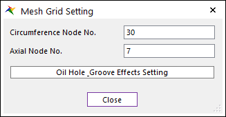
Figure 1 Mesh Grid Setting dialog box
•Axial Node No.: “M”
•Circumference Node No.: “N”
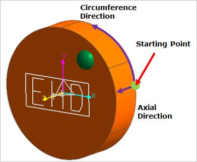
Figure 2 Defining Circumference Node No. and Axial Node No.
•Oil Hole & Groove Effects Setting
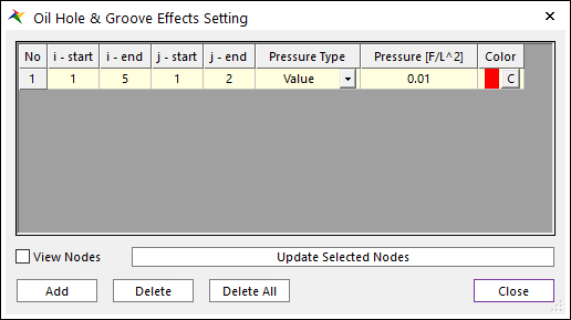
Figure 3 Oil Hole & Groove Effects Setting dialog box
•i-start: Defines start grid index in circumferential direction.
•i-end: Defines end grid index in circumferential direction.
•j-start: Defines start grid index in axial direction.
•j-end: Defines end grid index in axial direction.
•Pressure Type: Define pressure value on oil hole and groove region with constant value or time dependent expression.
•Pressure: Defines the pressure value.
•Color: Displays the selected nodes as this color if the user checks View Nodes.
•View Nodes: Shows the selected nodes in the Working Window.
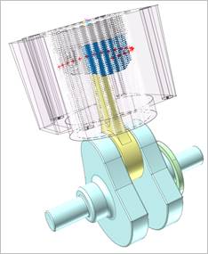
Figure 4 View Nodes
•Update Selected Nodes: The position of Oil Hole and Groove is changed.