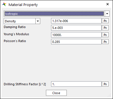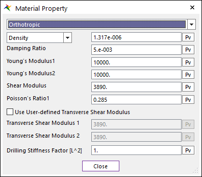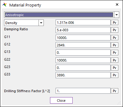
The Material Property dialog box is shown clicking Material Property in the Shell Belt dialog box. The shell belt supports 3 types of material. For more information, click here. The parameters are explained below. The parameters are explained below.

(a) Isotropic

(b) Orthotropic

(3) Anisotropic
Figure 1 Material Property dialog box
•Density or Total Mass: Allows you to choose the density or total mass of the belt.
•Damping Ratio( ): Defines the damping ratio. It has
the:
•Structural damping ratio of belt
•Damping matrix of C
They are computed from the following equation.

•Drilling Stiffness factor: Defines the multiplier factor of drilling stiffness. If the drilling of shell element is too flexible, the shell element is changed stiffer for the only drilling stiffness by enlarging the factor.
•Isotropic
Young’s Modulus and Poisson’s Ratio is set. In general, Shear Modulus is calculated from the Young’s Modulus and the Poisson’s Ratio in the isotropic material.
•Young's Modulus: Is the Young's Modulus of belt.
•Poisson’s Ratio: The shear modulus (G) is calculated.
•Orthotropic
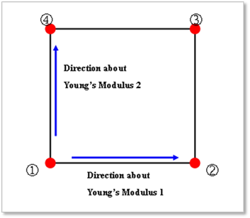
The orthotropic material is applied to the shell4.
o Young's Modulus 1: Young's Modulus of the orthotropic in the local direction by the local node 2 to the local node 1.
o Young's Modulus 2: Young's Modulus of the orthotropic in the local direction by the local node 4 to the local node 1.

o Shear Modulus (G): In-plane shear modulus.
o Poisson’s Ratio 1 (v1):
Note that 
o Use User-defined Transverse Shear Modulus: Defines the transverse shear modulus. If this check option is disabled, shear correction factor is used to obtain the transverse shear modulus, which is a default value for original orthotropic material (~V9R2). If checked, user can set the transverse shear modulus.
o Transverse Shear Modulus 1: Transverse shear modulus in direction 1 (G1z).
o Transverse Shear Modulus 2: Transverse shear modulus in direction 2 (G2z).
•Anisotropic
•G11 to G33 represents the component of constitutive matrix in shell material.