The link convertor can change a general body from one or more selected links in a track assembly. If the user uses this function in order to change one or more general link bodies in a closed loop track assembly, the selected link bodies are converted to the general bodies.
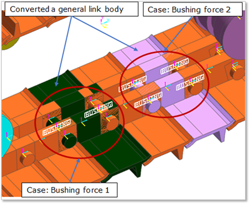
After using this function, the converted bodies are automatically connected to the adjacent links by the bushing connector. But, the contact connections among the general body and entities of track LM toolkit are separated. Therefore, the user must define the contact entities to the converted links with a sprocket, a flange, and a ground by the general contact function like as the Geo-contact.
The link convertor is for a FFlex link body. To see the modeling procedure for the flexible link in RecurDyn/Track_LM, refer to Example for generating a flexible link.

Figure 1 Link convertor icon of the Link group in the Track (LM) tab
Step to use Link Convert
1. Click the Converter icon of the Link group in the Track(LM) tab.
•Assembly, Track Link: One or more links of the assembly change into the general bodies.
•Assembly: All the links of the assembly change into the general bodies.
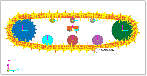
2. Select a track assembly. The Figure 1 shows the selected track assembly.

Figure 2 Selected track assembly
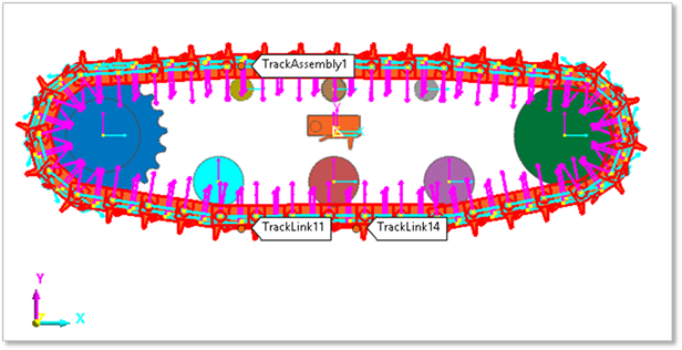
3. Select one or more links in the selected track assembly. Figure 2 shows the selected two link bodies.

Figure 3 Selected two link bodies.
4. Click Finish in the left top of the Working Window.
5. Select Number of Bushing Force. Figure 3 shows the dialog box for selecting the number of bushing forces.
•Single: If the user checks this option, the converted general body and the adjacent link body are connected with a bushing force.
•Double: If the user checks this option, the converted general body and the adjacent link body are connected with two bushing forces.

Figure 4 Dialog box for selecting the number of bushing force.

Figure 5 Location of the single and double bushing force