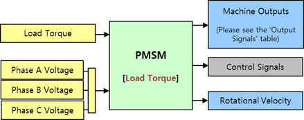
Figure 1 Input Port and Output Port of Load Torque Type
Input Signals
|
Port |
Input Signal |
Description | |
|
|
Load Torque |
|
The Load Torque. This value is used to calculate the Driving Torque in the Load Torque Type. [N] |
|
|
Phase A Voltage |
|
The Phase A Voltage. [V] |
|
Phase B Voltage |
|
The Phase B Voltage. [V] | |
|
Phase C Voltage |
|
The Phase C Voltage. [V] | |
Output Signals
|
Port |
Output Signal |
Description | |
|
|
Rotor Angle |
|
The Rotor Angle. [rad] |
|
Rotor Speed |
|
The Rotor Angular Speed. [rad/s] | |
|
Stator Current of Phase A |
|
The Stator Current of Phase A. [A] | |
|
Stator Current of Phase B |
|
The Stator Current of Phase B. [A] | |
|
Stator Current of Phase C |
|
The Stator Current of Phase C. [A] | |
|
Stator Current of d-Axis |
|
The Stator Current of d-Axis. [A] | |
|
Stator Current of q-Axis |
|
The Stator Current of q-Axis. [A] | |
|
Stator Voltage of d-Axis |
|
The Stator Voltage of d-Axis. [V] | |
|
Stator Voltage of q-Axis |
|
The Stator Voltage of q-Axis. [V] | |
|
Electrical Torque |
|
The Generated electrical torque. [N.m] | |
|
|
Control Signals |
|
This signal is used when you control the motor use the PMSM Driver block. When you use the PMSM Machine block, this port doesn`t export any signal. |
|
|
Rotational Velocity |
|
Rotor Rotational Velocity. [rad/s] |
Example
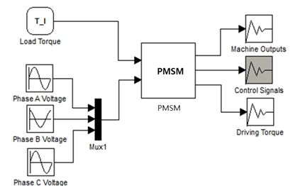
Figure 2 Example of Load Torque Type


