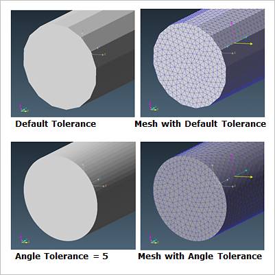
RecurDyn/Mesher uses the mesh core which includes the re-mesh function as the basic function. RecurDyn/Mesher uses generally the graphical tessellation data of geometry which is the rendering type in the screen. So, the mesh output is influenced by the accuracy of input data. If the mesh is performed roughly, it is ok to use the rough input data. But, if the mesh is performed finely, you will get the unnecessary data by the influence of input data. (Refer to below Figure 1).
•If you use the default option, the mesher inputs the data as the default state of Rendering option in RecurDyn.
•Do not control the Rendering option to mesh. To control the Rendering option in RecurDyn is not related to the input data.
•If there are the free lines and the free surfaces, you should properly control the precision of input data. Because the precision of input data affects the quality of mesh output. If the related tolerance is controlled finely more than needs, the performing time of mesh will be increased. Also, you will need the memory more than needs in the rendering kernel and will fail the mesh work.

Figure 1 Example of Tolerance

Figure 2 Geometry Refinement icon of the Mesher group in the Mesher tab

Figure
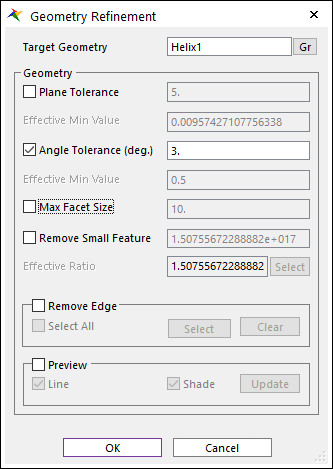
3 Geometry Refinement dialog box
•Target Geometry: Selects the geometry which performs the Geometry Refinement function.
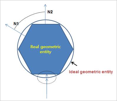
•Plane Tolerance: Defines the value of plane difference between a real and idea geometric entity. You can see this value in the inside of dotted line. This value is applied differently, based on the size of features. The unit is changed by Global Unit in RecurDyn.
•Angle Tolerance (deg.): Defines the value to the difference of angle between N1 and N2. This value is applied regardless of the size of features. The unit of this option is degree.
•Effective Min Value: Shows the effective min value of tolerances. It is better to input bigger values than to these values. If the user inputs smaller these values, it will take long time to see the preview and make mesh.

Figure 4 Definition for Plane Tolerance and Angle Tolerance
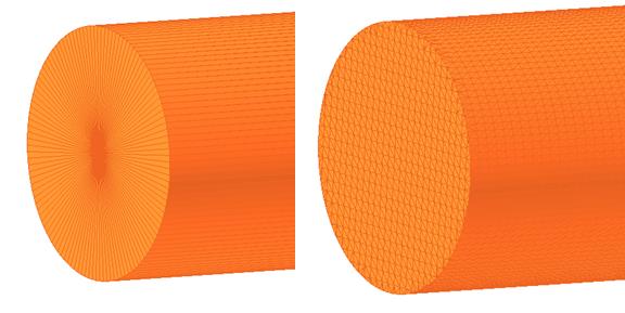
•Max Facet Size: It controls the limit size of the input data. If the input data is rough, it could be limited by this option.

Max Facet Size is not applied Max Facet Size is applied (10)
Figure 5 Use of Max Facet Size
•Remove Small Feature: Defines the value to the ratio of Bounding Box of the geometric entity. You can remove small features as compared with an entire geometric entity.
•Effective Ratio: If you select a small feature, you can check the ratio of selected feature. It helps to easily apply the ratio of small feature to remove.
•Remove Edge: If you have unnecessary edge while meshing, you can ignore some edges.
•Select All: ignore all edges
•Select: select some edges to ignore
•Clear: unselect some edges
•Preview: If this option is checked, the geometric entity which is applied to the setting values shown in the screen.
•Line: It shows the lines of the tessellation data that the options are applied.
•Shade: It shows the faces of the tessellation data that the options are applied in the shad mode.
•Update: Updates the setting values.
Note
Advanced Mesh uses original geometry, unlike auto-mesh which uses tessellation data. Therefore, in Advanced Mesh, Geometry Refinement function does not work.