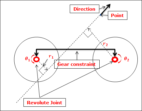
A gear can be used to relate relative coordinates of two revolute joints. The user can define the gear ratio by attaching a common velocity marker on the carrier body to which the joints are attached. The z-axis of the common velocity marker is defined by clicking two points [Point and Direction]. Therefore, the user must define the base markers of two revolute joints and the common velocity marker on the same carrier body. The z-axis of the common velocity marker becomes the tangential velocity direction of the two action bodies of revolute joints.
Figure 1 Configuration of Gear Joint
The formula for the gear constraint is
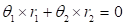
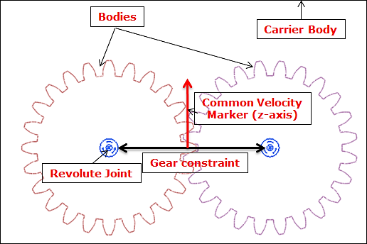
Figure 2 Formula for Gear Joint
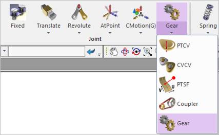
Figure 3 Gear icon of the Joint group in the Professional tab
A gear joint is different with a coupler as follow.
•A gear joint can define two revolute joints only.
•The base body of two revolute joints must be same.
•A point is defined instead of a scale.