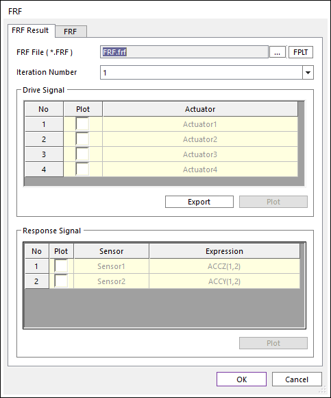
Using this dialog, user can check the FRF, inverse FRF, Actuator signals and, Sensor Signals. In order to check, the “*.FRF” file is needed.
Figure 1 FRF dialog box [FRF Result tab]
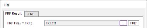
Figure 2 FRF File setting
•FRF File (*.FRF): Defines “*.FRF” file by clicking ….
•FPLT: Checks the FRF and the inverse FRF functions with Plot windows.
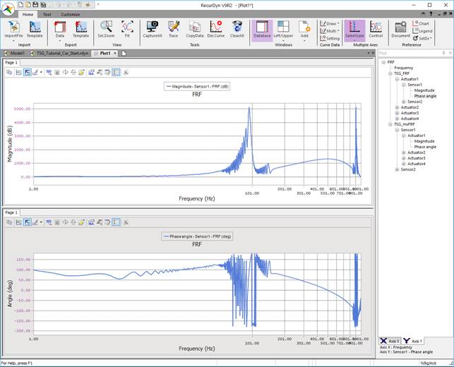
Figure 3 Plot view for FRF and Inverse FRF by clicking FPLT
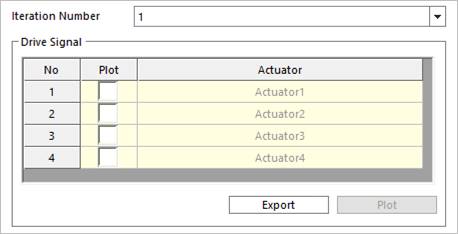
Figure 4 Drive Signal region on the FRF Result tab
•Iteration Number: Defines the Iteration Number. Iteration Number means the simulation count value for computing FRF. And the Iteration Number is always the same with the number of Actuator channels.
•Drive Signal
•Plot check box in list view
•Export: Generate “*.TAI” file including the Actuator signals on time domain.
•Plot: User can see the signal data on the opened scope dialog.
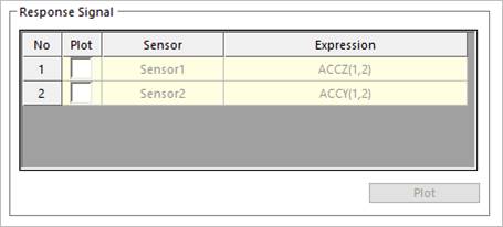
Figure 5 Response Signal region on the FRF Result tab
•Response Signal
•Plot check box in list view
•Plot: User can see the signal data on the opened scope dialog.