
User can set a FRA Input Channel and FRA Output Channel.
•FRA Input is Force/Torque which is provided as FX, FY, FZ, TX, TY and TZ.
•FRA Output is provided as TX, TY, TZ, RX(Roll), RY(Pitch), RZ(Yaw), VX, VY, VZ, WX, WY, WZ, ACCX, ACCY, ACCZ, WDTX, WDTY, WDTZ, TM, VM, WM, ACCM, and WDTM.
Figure 1 Exc.RFlex icon of the FRA group in the Flexible tab
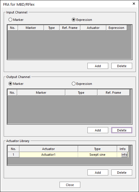
Figure 2 FRA for MBD/RFlex dialog box
•Input Channel
There are two types as Marker and Expression.
•Marker type
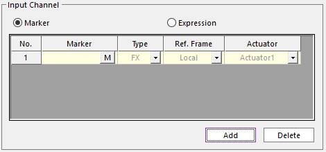
Figure 3 Marker type of the FRA Input
o Marker: User can select a marker.
o Type: FX, FY, FZ, TX, TY, and TZ
o Reference Frame: There are two options as Local and Global. Local reference frame means that the X, Y, and Z axis of input force or roque is defined as the selected marker. Global reference frame means that the X, Y, and Z axis of input force or torque is defined as the ground inertia marker.
o Actuator: User can select an actuator in the actuator library.
•Expression type
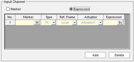
Figure 4 Expression type of the FRA Input
o Marker, Type, Ref. Frame, and Actuator: Refer to Marker type of FRA input.
o Expression: User can set of magnitude value of the FRA input force/torque with an expression. This value can be set in Expression type of FRA input.
•Output Channel
•Marker type
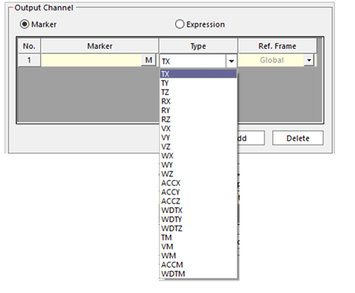
Figure 5 Marker type of the FRA Input
o Marker: User can select a marker.
o Type: TX, TY, TZ, RX, RY, RZ, VX, VY, VZ, WX, WY, WZ, ACCX, ACCY, ACCZ, WDTX, WDTY, WDTZ, TM, VM, WM, ACCM, and WDTM.
o Ref. Frame: There are two options as Local and Global. Local reference frame means that the X, Y, and Z axis of input force or roque is defined as the selected marker. Global reference frame means that the X, Y, and Z axis of input force or torque is defined as the ground inertia marker.
•Expression
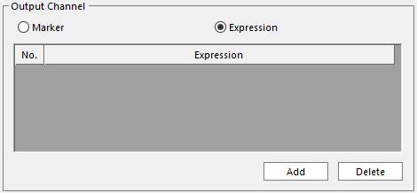
Figure 6 Expression type of the FRA Output
o User can freely make an FRA output channel with the expressions. For more information about Expression, click here.
•Actuator Library
An actuator is created by default named “Actuator1”.
•Actuator: User can set and modify the name.
•Type: There’s only one type named “Swept Sine”. Swept Sine is consistent for two parameters as magnitude and phase angle. In order to set the parameters, click Info.
•Info: User can set and modify the parameters of the selected actuator. These parameters will influence to the “Frequency Response with Actuator” of the FRA Plot data.
o Force Magnitude: Is a dimensionless magnitude factor for the actuator input. This factor is multiplied to the Input channel.
o Phase Angle: Is a shift angle for the actuator input. This angle shifts the phase of Input channel. The unit is a degree.
o For example, if the input is
 , Force Magnitude is
  , and Phase angle is
  , then the result response (
 ) will be evaluated as
  . Here,
 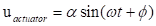 .
.
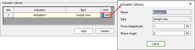
Figure 7 Actuator Library