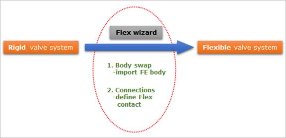
Flex wizard helps the user to design the valve system with nodal flexible bodies.
•Flex wizard supports two functions such as Body Swap and Connection.
•So, given a complete valve system with only rigid bodies, you can swap several rigid bodies to their nodal flexible bodies and define their flex contacts through Flex wizard.
•In Body Swap, the FE input file (NASTRAN or ANSYS) should be prepared so that a nodal flexible body may be exactly imported at SPM of its rigid body.
•In Connections, Flex contact is automatically defined according to what body is swapped.
Figure 1 Concept of Flex wizard
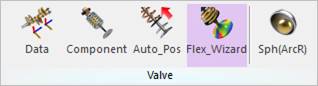
Figure 2 Flex_Wizard icon of the Valve group in the Valve tab
1. Click the Flex_Wizard icon of the Valve group in the Valve tab.
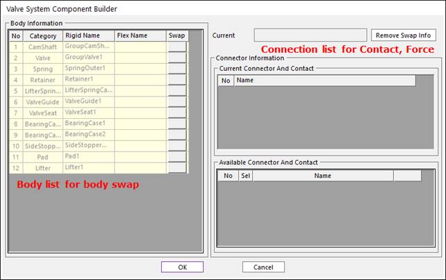
Figure 2 Valve System Component Builder dialog box
2. Select the FE seat input file for Body Swap.
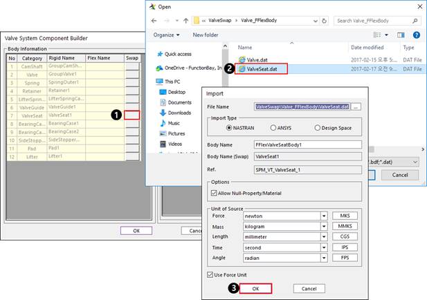
Figure 3 Body swap
3. Select the Flex Contact between the Valve and FE seat.
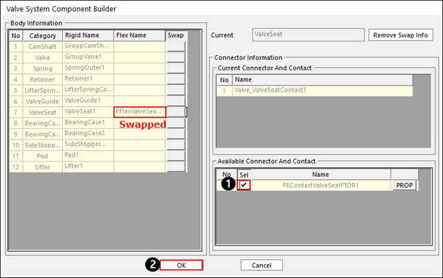
Figure 4 Flex contact definition
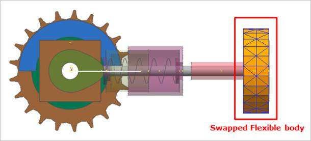
Figure 5 Valve system with FE seat
4. Optionally, the user can control Display option of FE seat. Refer to Components & Sets Dialog in FFlex.
5. Modify the property of Flex Contact. For more information, refer to FSurface To Surface Contact in FFlex.
6. Go to Edit the model of FE seat body to modify the patch set, material, display option and define the BC, Output node. For more information, refer to Edit Functions for FFlexBody in FFlex.
7. Click the Dyn/Kin icon of the Simulation Type group in the Analsys tab for Dynamic Analysis.
8. View the contour result.
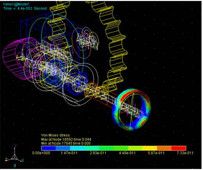
Figure 6 Contour